Primary and Secondary Flight Controls
Identify what each control surface does, distinguish high-lift and drag devices from trim surfaces, follow a pilot command through different control-system architectures, and reason carefully about failures.
1. Primary controls: command the three rotations
On a conventional fixed-wing aircraft, the primary flight controls are the ailerons, elevator (or an equivalent pitch surface) and rudder. Their principal roles are roll, pitch and yaw. “Primary” describes their role in attitude control; it does not mean they are the only surfaces that can influence those motions.
| Control | Typical location | Principal rotation | Typical pilot input |
|---|---|---|---|
| Ailerons | Outboard trailing edge of the wings | Roll about the longitudinal body axis | Control wheel / stick left or right |
| Elevator | Movable part of the horizontal tail | Pitch about the lateral body axis | Control column / stick forward or aft |
| Rudder | Movable part of the vertical tail | Yaw about the vertical body axis | Rudder pedals |
| Stabilator | All-moving horizontal tail | Pitch about the lateral body axis | Pitch control, with aircraft-specific feel / trim features |


Command chain: cockpit input → linkage or signal path → actuator / mechanical transmission → surface deflection → aerodynamic force → moment about the centre of gravity → aircraft angular response. The exact chain varies by aircraft.
2. Deflection creates aerodynamic force and moment
A deflected surface changes the local shape presented to the airflow. The resulting pressure distribution produces a force; its moment about the aircraft’s centre of gravity changes angular motion. Airspeed, density, surface area, lever arm, deflection, geometry and configuration all affect the response.
Dynamic pressure: q̄ = ½ ρV²
Generic aerodynamic moment: M = q̄ S c C
Control-surface hinge moment: H = q̄ Sc cc Ch
Here ρ is air density, V airspeed, S a reference area, c a reference length, and the relevant coefficient is dimensionless. The signed coefficient follows the stated convention.
The equations show why a surface can feel harder to move as aerodynamic loading rises. Real control-force and actuator calculations also depend on hinge geometry, balance features, gearing, friction and system design; this simple relation is for conceptual study.
Worked hinge-moment calculation
Let q̄ = 2,500 N/m², control-surface area Sc = 1.8 m², chord cc = 0.35 m and coefficient Ch = −0.06.
H = 2,500 × 1.8 × 0.35 × (−0.06) = −94.5 N·m. The hinge-moment magnitude is 94.5 N·m. Interpret the negative sign only using the problem’s stated sign convention; it does not universally mean “nose-down” or “restoring.”
Dimension check: (N/m²) × m² × m = N·m, the unit of moment. Deflection angles may be expressed in degrees or radians, but derivatives such as ∂Ch/∂δ must use the matching angular unit.
3. Secondary controls: change lift, drag or handling
Secondary or auxiliary controls modify wing performance, drag, trim or pilot effort. Terminology can differ between references and aircraft manuals; identify a device by its location, motion and function, and follow the aircraft-specific description.
| Device | Location / movement | Main effect | High-value distinction |
|---|---|---|---|
| Trailing-edge flap | Trailing edge; usually moves down, sometimes translates | Changes camber (and on some designs effective area); increases lift and commonly drag | High-lift device; configuration and setting matter |
| Leading-edge slat | Leading edge; extends to form a slot / altered nose geometry | Helps delay separation and support higher angle of attack and lift | Leading-edge device; not a trim tab |
| Spoiler | Panel rises from wing upper surface | Disrupts flow, reduces lift and adds drag | May dump lift on landing or augment roll on some aircraft |
| Speed brake | Dedicated panel or spoiler surface, depending on aircraft | Primarily adds drag to reduce speed or increase descent rate | Function name; spoiler and speed brake can share hardware |
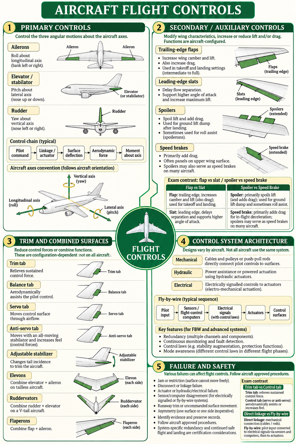
• Flap vs slat: trailing-edge camber change vs leading-edge flow/separation support.
• Spoiler vs speed brake: lift destruction plus drag vs primarily drag; one spoiler surface may perform both roles.
• Approach vs landing: flight spoilers / speed brakes and ground lift-dump logic are aircraft-configured; do not assume identical deployment.
Configuration caution: High-lift devices change lift, drag and pitching moments. Their schedules, asymmetry protection and limitations are aircraft-specific; do not infer a safe setting from a generic diagram.
4. Trim tabs and combined-purpose surfaces
Some auxiliary surfaces reduce control force; others combine two control functions in one physical surface. Names describe different aerodynamic or control roles, so avoid treating every small tab as a trim tab.
| Device | Typical role | Exam distinction |
|---|---|---|
| Trim tab | Creates a balancing aerodynamic effect to relieve sustained pilot force or set trim | Trim changes the balance / neutral condition; it does not replace the primary control |
| Balance tab | Aerodynamically assists movement of its parent surface | Assists pilot effort; not automatically a trim device |
| Servo tab | Tab aerodynamic force helps move the larger parent control | The pilot/control path may move the tab rather than directly drive the main surface |
| Anti-servo tab | On common stabilators, moves with the surface to increase force / feel | Different purpose from a force-relieving trim tab |
| Spring tab | Uses spring / aerodynamic loading to assist control at higher loads on certain designs | Not interchangeable with a trim tab; arrangement is aircraft-specific |
| Adjustable stabilizer | Changes tailplane incidence and pitching balance | Moves the stabilizer assembly rather than only a small trailing-edge tab |
| Surface name | Combined functions | Typical configuration |
|---|---|---|
| Elevon | Elevator + aileron | Tailless / delta-wing aircraft |
| Ruddervator | Rudder + elevator | V-tail aircraft |
| Flaperon | Flap + aileron | Some aircraft; trailing-edge surface supports both functions |
| Stabilator | All-moving pitch-control tailplane | Aircraft using a movable horizontal tail as the pitch surface |
Remember: A combined surface is not a new fourth axis. It supplies more than one control function; the aircraft’s mixing system determines how input maps to surface motion.
5. How the command reaches the surface
| Architecture | Command / power path | What to distinguish |
|---|---|---|
| Mechanical | Cables, pulleys, bellcranks, push-pull rods or torque tubes transmit pilot motion | Physical linkage does not necessarily mean the pilot alone supplies all force |
| Hydraulic power-assisted / powered | Hydraulic pressure supplies actuator force; command may remain mechanical, electrical or mixed | Hydraulic power source is distinct from how the command is sent |
| Electrically signalled / electro-mechanical | Electrical signal commands an actuator; the actuator may be electric, hydraulic or electrohydraulic | Electrical signalling does not imply one universal actuator type |
| Fly-by-wire (FBW) | Pilot input is sensed/processed; computers issue electrical commands to actuators under control laws | May include feedback, redundancy, mode logic and envelope protections; details vary |
Typical fly-by-wire signal path
Pilot input → input sensors → flight-control computers / control laws → electrical command → actuator → surface → position / system feedback. A specific aircraft may use multiple computers, power sources and actuator types, and the actual modes and backup paths must be learned from its approved documentation.
Exam trap: Mechanical, hydraulic and fly-by-wire are not always mutually exclusive labels. A system may use hydraulic actuator power with electrical command signals, or mechanical backup within an otherwise electronically controlled architecture.
6. Failure modes, redundancy and safety review
| Failure / anomaly | Possible generic consequence | Evidence / design questions |
|---|---|---|
| Jam or restriction | Reduced, biased or unavailable surface travel | Which surface, travel direction, linkage, hinge and flight condition? |
| Disconnect / broken linkage | Command may not reach the surface; surface position may be uncertain | Where did continuity fail? Is another path present? |
| Actuator / hydraulic / electrical fault | Surface movement may be lost, slowed, limited or uncommanded | Which power and command channels are affected? What feedback / alert appeared? |
| Runaway trim | Uncommanded continued trim movement changes aircraft balance | Trim command, position, alert, electrical supply and approved response procedures |
| Asymmetric / uncommanded surface | Unwanted moment, drag or handling change | Surface position history, actuator state, sensor data and maintenance evidence |
| Sensor / computer disagreement | Degraded, alternate or changed control law on some systems | System mode, fault messages, redundant input agreement and aircraft-specific logic |
Redundancy uses alternate channels, components, power paths or control capability to reduce the effects of selected failures. It does not prove that a fault is harmless: common-mode faults, damage, jams and combinations of failures must be assessed against the actual system design and certification basis.
Air Safety Officer review sequence
- Record the time sequence, aircraft configuration, flight phase and crew description.
- Preserve available recorded indications/data, technical logs, deferred defects, maintenance actions and physical evidence.
- Identify the affected surface, command path, actuator/power path, feedback and any asymmetry.
- Separate observed evidence from inferred cause; avoid declaring a system safe or unsafe from a generic diagram.
- Use the aircraft maintenance/flight manuals and applicable approved procedures for the real aircraft.
Operational boundary: This lesson explains concepts; it is not an abnormal/emergency checklist. Aircraft-specific symptoms, alternate modes and required actions must come from approved aircraft documentation.
Quick recall
- Aileron → roll; elevator / stabilator → pitch; rudder → yaw (principal conventional mapping).
- Flap: trailing-edge high-lift device; slat: leading-edge separation-delay aid.
- Spoiler reduces lift and adds drag; speed brake is primarily for drag, and may use spoiler hardware.
- Trim reduces sustained force; balance and servo tabs can assist surface motion; anti-servo tabs commonly increase stabilator feel.
- Elevon = elevator + aileron; ruddervator = rudder + elevator; flaperon = flap + aileron.
- Electrical command path and actuator power source are separate design questions.
- For any failure, identify affected surface, command path, power, feedback, redundancy and approved procedures.
Further reading
- FAA Pilot’s Handbook of Aeronautical Knowledge — Chapter 6: Flight Controls, for primary/secondary controls, trim and control systems.
- FAA Airplane Flying Handbook — Chapter 16, for spoilers and speed-brake purposes and aircraft-specific procedures.
- NASA Glenn — Airplanes: Parts and control surfaces, for introductory surface diagrams and functions.
- FAA Lessons Learned — Boeing 737 flight-control system safety case, for certification-level discussion of flight-control failure, jam and redundancy considerations.
UPSC-style self assessment
38 questions on Topic 1.5
Includes direct concept checks, statement analysis, assertion–reason, matching, application and one worked-unit calculation. Select an option, check it, then read the explanation.
A. Primary controls and response
Q01.Which pairing correctly identifies a conventional primary flight control and its principal rotation?
Reveal answer and explanation
Answer A. Ailerons primarily command roll, elevators pitch, and rudders yaw. The axis named is the line about which the aircraft rotates.
Q02.A pilot moves the control column aft in a conventional airplane. Which response is normally commanded?
Reveal answer and explanation
Answer B. Aft column movement normally commands nose-up pitch through the elevator or an equivalent pitch-control surface. The precise linkage and surface arrangement vary by aircraft.
Q03.Consider these statements: 1. The rudder primarily controls yaw. 2. The elevator primarily controls pitch. 3. The ailerons primarily control roll. Which are correct for a conventional fixed-wing airplane?
Reveal answer and explanation
Answer D. All three pairings describe the conventional primary control mapping. Coupling can create secondary responses about other axes.
Q04.Which sequence best represents how a pilot command produces aircraft rotation?
Reveal answer and explanation
Answer B. The control path moves a surface; airflow produces a force whose moment about the centre of gravity changes angular motion.
Q05.A control surface is deflected while the aircraft is moving through air. What directly produces its aerodynamic effect?
Reveal answer and explanation
Answer C. The surface changes the local airflow and pressure distribution. The resulting aerodynamic force and moment affect the aircraft.
Q06.Why is “one control surface always affects only one axis” an unsafe generalization?
Reveal answer and explanation
Answer B. The conventional primary mapping describes the principal effect. Coupling, configuration, control laws and combined surfaces can add other effects.
B. High-lift and drag devices
Q07.Which statement best describes the usual effect of trailing-edge flaps?
Reveal answer and explanation
Answer A. Flaps change the wing section and lift characteristics; they usually also add drag. The amount and effect depend on flap type and setting.
Q08.A leading-edge slat is extended. What is its main aerodynamic purpose?
Reveal answer and explanation
Answer B. A slat forms or opens a leading-edge slot that helps maintain more attached flow at higher angles of attack, increasing usable maximum lift on suitable designs.
Q09.Which pairing distinguishes a spoiler from a speed brake most accurately?
Reveal answer and explanation
Answer B. Spoilers reduce lift and add drag. A speed brake is classified by its drag-producing purpose; spoiler panels may also serve that purpose on some aircraft.
Q10.Why are ground spoilers commonly deployed after touchdown on aircraft so equipped?
Reveal answer and explanation
Answer B. Spoiling lift after touchdown increases wheel loading and the effectiveness of wheel braking; spoilers also add aerodynamic drag.
Q11.Which statement about speed brakes is correct?
Reveal answer and explanation
Answer A. Speed brakes are drag devices. Whether they are separate panels or spoiler surfaces, and how they may be used, is aircraft-specific.
Q12.On an aircraft whose spoilers augment roll control, how can spoiler extension contribute to roll?
Reveal answer and explanation
Answer A. Differential spoiler action can reduce lift on one wing and help produce roll. This is a design feature on some aircraft, not a universal function.
Q13.Match each device to its usual function: 1. Slat 2. Flap 3. Ground spoiler 4. Speed brake; a. increase camber/lift for low-speed configuration b. help delay separation at higher angle of attack c. reduce lift after touchdown d. primarily add drag in flight.
Reveal answer and explanation
Answer A. Slats support attached flow at higher angle of attack; flaps alter camber and lift; ground spoilers dump lift; speed brakes primarily add drag.
Q14.Which statement is NOT generally correct about flaps and slats?
Reveal answer and explanation
Answer D. Flap effects depend on design and setting, and increased lift commonly comes with increased drag. There is no universal flap response independent of configuration.
C. Trim and combined surfaces
Q15.What is the primary purpose of a conventional trim system?
Reveal answer and explanation
Answer A. Trim changes the balance of forces or the control-system neutral condition so the pilot need not continuously hold a control force. It does not replace normal control.
Q16.A balance tab is designed mainly to:
Reveal answer and explanation
Answer A. A balance tab uses aerodynamic force on the tab to assist the parent surface. Tab direction and linkage depend on the particular design.
Q17.How does a servo tab commonly help move a larger control surface?
Reveal answer and explanation
Answer A. A servo tab can use aerodynamic force to move the main control surface, reducing the force required through the control path.
Q18.An anti-servo tab on an all-moving stabilator commonly:
Reveal answer and explanation
Answer A. An anti-servo tab moves in the same direction as the stabilator on typical installations, increasing control force and feel. The design is aircraft-specific.
Q19.What does an adjustable horizontal stabilizer do when used for trim?
Reveal answer and explanation
Answer A. An adjustable stabilizer changes the tailplane incidence and associated pitching moment; it is not simply a small trim tab.
Q20.Assertion (A): A trim tab can reduce the continuous force needed to hold a selected flight condition. Reason (R): A tab changes local aerodynamic forces and can establish a balancing moment.
Reveal answer and explanation
Answer A. Both are true. The aerodynamic effect of the tab can create a balancing moment that reduces the sustained force needed at the main control.
Q21.Which statement correctly defines an elevon?
Reveal answer and explanation
Answer A. Elevons combine pitch and roll control functions. Their mixing and movement depend on aircraft design.
Q22.A V-tail aircraft uses ruddervators. These surfaces combine:
Reveal answer and explanation
Answer A. Ruddervators combine pitch and yaw control functions, with control inputs mixed to produce the required response.
D. Control-system architecture
Q23.Which architecture normally carries pilot movement through cables, bellcranks or push-pull rods toward a control surface?
Reveal answer and explanation
Answer A. A mechanical system transmits input through physical linkages. Power assistance may be added while retaining mechanical paths.
Q24.What is the main role of hydraulic power in a powered flight-control system?
Reveal answer and explanation
Answer A. Hydraulic pressure can power an actuator that moves a control surface. The command path and backup design vary by aircraft.
Q25.“Electrically signalled” controls necessarily mean the surface is moved by an electric motor alone. Is this statement correct?
Reveal answer and explanation
Answer B. Signal transmission and actuator power are separate design choices. An electrical command may ultimately drive different actuator types.
Q26.Which sequence best describes a typical fly-by-wire command path?
Reveal answer and explanation
Answer A. Fly-by-wire uses electrical signalling and flight-control computers between pilot input and actuators. Specific architectures differ.
Q27.What is the purpose of redundancy in a flight-control system?
Reveal answer and explanation
Answer A. Redundant channels/components can preserve function after some failures. Redundancy does not mean immunity to common-mode faults or every possible failure.
Q28.Which distinction between a control command and an actuator is correct?
Reveal answer and explanation
Answer A. The command path determines a desired movement; an actuator converts supplied energy into mechanical movement. Feedback and monitoring may verify response.
Q29.Why does mode awareness matter on an aircraft with multiple flight-control laws or modes?
Reveal answer and explanation
Answer A. Control laws and available protections may change with system mode or failures; crews need to recognize the actual mode and approved procedures.
E. Failures and safety
Q30.A safety report notes that an elevator was restricted during a ground check. What is the best generic conclusion?
Reveal answer and explanation
Answer A. A restriction can reduce or bias control. It is not possible to infer controllability or operational action without aircraft-specific inspection and approved procedures.
Q31.A broken control linkage is found during an investigation. Which effect is most technically defensible?
Reveal answer and explanation
Answer A. A disconnect can interrupt command transmission, but the surface position and remaining authority depend on architecture, actuator arrangement and failure location.
Q32.A hydraulic actuator failure is reported. Which assessment should come first?
Reveal answer and explanation
Answer A. Effects depend on system segregation, actuator arrangement and backup capability. Records and approved aircraft information are needed to assess it.
Q33.What best describes runaway trim?
Reveal answer and explanation
Answer A. Runaway trim is unwanted continued trim-system movement. Recognition, response and available cut-outs are aircraft-specific and belong to the approved flight manual.
Q34.Why is an asymmetric control-surface position potentially hazardous?
Reveal answer and explanation
Answer A. Asymmetry can generate an unintended moment and drag. Consequences vary with surface, speed, aircraft and system design.
Q35.During a control-system occurrence review, which evidence set is most useful to preserve first?
Reveal answer and explanation
Answer A. A defensible review preserves time-linked operational and maintenance evidence, recorded data where available, and physical findings before drawing conclusions.
Q36.A control surface has area S = 1.8 m², characteristic chord c = 0.35 m, dynamic pressure q̄ = 2,500 N/m², and hinge-moment coefficient Cₕ = −0.06. Using H = q̄ScCₕ, what is the signed hinge moment?
Reveal answer and explanation
Answer A. H = 2,500 × 1.8 × 0.35 × (−0.06) = −94.5 N·m. The sign depends on the stated coefficient convention; magnitude is 94.5 N·m.
Q37.On an aircraft fitted with a spring tab, which statement best describes its usual role?
Reveal answer and explanation
Answer A. A spring tab can use spring coupling and aerodynamic loading to assist control movement when hinge loads are high. Its linkage and behavior vary by aircraft; it is not automatically a trim tab.
Q38.A trailing-edge surface is called a flaperon. Which description is most accurate?
Reveal answer and explanation
Answer B. A flaperon is a combined flap/aileron surface. It can contribute to lift configuration changes while providing roll control through aircraft-specific surface mixing.
15-minute timed challenge · 10 questions · +3 / −1
The challenge samples 10 questions from the same 38-question bank. Start when ready; unanswered questions score zero.
Fast recall before practice
Revision tables: all Topic 1.5 concepts
Review control roles, device distinctions, command paths, failure categories, formula units and exam traps in compact tables.
1. Primary controls and axis mapping
| Control | Primary motion | Axis | Control input |
|---|---|---|---|
| Ailerons | Roll | Longitudinal | Wheel / stick left–right |
| Elevator | Pitch | Lateral | Column / stick fore–aft |
| Rudder | Yaw | Vertical | Pedals |
| Stabilator | Pitch | Lateral | All-moving tail; may use anti-servo / trim features |
2. High-lift and drag devices
| Device | Position | Main effect | Exam trap |
|---|---|---|---|
| Flap | Trailing edge | Changes camber / sometimes area; increases lift and usually drag | Not the primary roll control |
| Slat | Leading edge | Helps delay flow separation at higher angle of attack | Not the same as a trailing-edge flap |
| Spoiler | Wing upper surface | Spoils lift and adds drag; may aid roll | May also act as a speed brake |
| Speed brake | Dedicated panel or spoiler | Primarily adds drag | Purpose/function need not equal unique hardware |
| Ground spoiler | Wing spoiler after touchdown | Reduces lift; increases wheel loading and drag | Activation logic is aircraft-specific |
3. Tabs and trim surfaces
| Device | Recall cue | Avoid confusing it with |
|---|---|---|
| Trim tab | Relieves sustained control force / adjusts trim | Primary control or universal emergency backup |
| Balance tab | Aerodynamic assistance to parent surface | A tab always operated as trim |
| Servo tab | Tab force can move main control surface | Simple position indicator |
| Anti-servo tab | Commonly moves with stabilator to increase feel | Force-relieving trim tab |
| Spring tab | Assists controls under higher aerodynamic load on certain designs | One universal direction / arrangement |
| Adjustable stabilizer | Changes tailplane incidence | Small trailing-edge tab only |
4. Combined surfaces
| Name | Combination | Typical application |
|---|---|---|
| Elevon | Elevator + aileron | Tailless aircraft |
| Ruddervator | Rudder + elevator | V-tail |
| Flaperon | Flap + aileron | Aircraft integrating both wing functions |
| Stabilator | All-moving pitch surface | Alternative to hinged elevator arrangement |
5. Architecture and signal / power distinction
| System element | What it does | Remember |
|---|---|---|
| Mechanical linkage | Transmits movement with cables, rods, bellcranks, pulleys | Pilot input path |
| Hydraulic actuator | Supplies movement force using hydraulic pressure | Actuation power source |
| Electrical command | Transmits requested movement as a signal | Does not by itself define actuator type |
| Fly-by-wire | Computer-mediated electrical command and control laws | Check mode, redundancy, feedback and backup paths |
6. Fault recognition and safety analysis
| Fault | Possible effect | Review first |
|---|---|---|
| Jam / restriction | Limited or biased surface movement | Surface, linkage, travel, condition |
| Disconnect | Command interrupted; surface position uncertain | Failure location, alternate paths |
| Actuator / power fault | Lost, reduced or uncommanded movement | Power source, circuit separation, feedback |
| Runaway trim | Uncommanded trim-state change | Recorded command, position, alert and system design |
| Asymmetry | Unintended force, moment and drag | Surface history, actuator and sensor data |
| Redundancy | Alternate ability after selected failure | Common-mode failure and actual certification/design basis |
7. Formula, quantities and units
| Relationship / quantity | Meaning | Unit / caution |
|---|---|---|
| q̄ = ½ρV² | Dynamic pressure | N/m² in SI |
| M = q̄ScC | Generic aerodynamic moment | N·m if S is m² and c is m |
| H = q̄ScccCh | Control-surface hinge moment | N·m; sign follows convention |
| Deflection δ | Angular displacement | Degrees or radians; match derivative units |
| Hinge moment coefficient Ch | Dimensionless coefficient | Negative sign is not a universal nose-up/down label |
8. Active recall cards
What are the three conventional primary controls?
Ailerons for roll, elevator / stabilator for pitch, and rudder for yaw.
Flap versus slat?
Flap is at the trailing edge and changes camber / lift; slat is at the leading edge and helps delay separation at higher angle of attack.
Spoiler versus speed brake?
A spoiler spoils lift and adds drag; a speed brake is primarily intended to add drag. A spoiler may serve as a speed brake.
Trim tab versus balance tab?
A trim tab relieves sustained control force; a balance tab aerodynamically assists its parent surface. Aircraft linkages can vary.
What does a typical anti-servo tab do?
On common stabilator installations it moves with the all-moving surface and increases control force / feel.
Define elevon, ruddervator and flaperon.
Elevon = elevator + aileron; ruddervator = rudder + elevator; flaperon = flap + aileron.
What does fly-by-wire describe?
An electrically signalled, computer-mediated command path to actuators; it does not mean that every aircraft uses the same actuator or backup arrangement.
What should a safety reviewer never infer from “jam” alone?
The exact remaining control or safe response. Identify the affected system, evidence, aircraft configuration and approved procedures.
9. High-Yield Mnemonics, Examination Traps & Fast Solving Tricks
Master trim tab deflection rules, secondary high-lift devices, and flight control safety architectures for Topic 1.5.
| Mnemonic / Hook | Concept & Pointwise Mechanics | 5-Second Recall Rule |
|---|---|---|
| TRIM TAB OPPOSITE |
|
To hold elevator DOWN (nose down) → Trim tab moves UP! To hold elevator UP (nose up) → Trim tab moves DOWN! |
| ANTI-SERVO = SAME DIRECTION |
|
Balance Tab = Opposite direction (reduces stick force). Anti-Servo Tab = Same direction (increases stick force / feel). |
| FOWLER FLIES FURTHER |
|
Highest lift increase (ΔCL,max) + increases wing area = Fowler Flap. |
| SLOTS SAVE SEPARATION |
|
Delays stall to significantly higher α without altering αL=0 = Slat / Slot. |
Examiner Traps & Rapid Elimination Tricks
| Common UPSC Trap | Misconception Statement | Actual Technical Reality | Fast Solving Heuristic |
|---|---|---|---|
| Trap 1: Trim Tab Direction | "To trim the aircraft for a pitch-up attitude, the trim tab on the elevator must deflect upwards." | FALSE. To pitch nose-up, the elevator trailing edge must be held UP. To hold the elevator up aerodynamically, the trim tab must deflect DOWN (generating an upward aerodynamic moment on the elevator trailing edge). | Elevator direction and trim tab direction are always INVERTED for conventional trim! |
| Trap 2: Slot vs Slat Distinction | "A leading-edge slot is a movable surface deployed on tracks." | FALSE. The slot is the aerodynamic passage or gap between the auxiliary airfoil and the main wing. The slat is the movable aerodynamic surface that extends forward to open the slot. | Movable surface = Slat. Air passage / gap = Slot. |
| Trap 3: Slat vs Flap on Lift Curve | "Deploying leading edge slats shifts the zero-lift angle of attack αL=0 to the left." | FALSE. Trailing-edge flaps increase camber, shifting the CL-α curve upwards and to the left (more negative αL=0). Leading-edge slats primarily extend the linear curve to a much higher αstall and higher CL,max with minimal change to αL=0. | Flap = Shifts curve left (αL=0 more negative). Slat = Extends curve upward/right to higher αstall. |
| Trap 4: Spoiler Roll Adverse Yaw | "Using roll spoilers to assist ailerons produces adverse yaw." | FALSE. Raising a spoiler on the down-going wing dumps lift AND creates substantial profile drag on that wing, pulling the nose into the turn (proverse yaw)! | Spoiler roll assist produces proverse yaw (or eliminates adverse yaw entirely)! |
UPSC Air Safety Officer Examination Pro-Tips: Flight Control Failure Protocols
- Runaway Stabilizer Trim: Uncommanded continuous deflection of the horizontal stabilizer. Memory item response: Hold control column firmly, disengage autopilot, activate electric trim cutout switches to disconnect power, and hand-crank manual trim wheel.
- Asymmetric Flap Deployment: One flap extends while the other remains retracted or jams. Produces severe rolling and yawing moments. Action: Immediately reverse flap lever to prior setting, do NOT cycle flaps further, and plan landing at higher approach speed (VREF).
- Ground Spoiler Interlock Safety: Ground spoilers dump wing lift and transfer vehicle weight to landing gear for maximum wheel braking friction. Interlocked to weight-on-wheels (squat switch) and wheel spin-up sensors to prevent catastrophic in-flight deployment.