Flight Axes, Coupled Motion and Stability Modes
Learn which way an aircraft rotates, how body axes differ from the horizon and airflow, why aileron input can produce yaw, and how Dutch roll differs from spiral instability.
1. Set up the aircraft reference frame
To describe rotation, imagine three mutually perpendicular reference axes through the aircraft’s centre of gravity (CG). The body axes are fixed to the aircraft: they turn as the aircraft turns. The CG is the useful reference origin for moments, although its location can change as loading changes.
| Body axis | Direction | Rotation about that axis | Short rate symbol |
|---|---|---|---|
| Longitudinal X | Nose to tail (along the fuselage) | Roll: the wings rotate up/down relative to the horizon | p |
| Lateral Y | One side of the aircraft to the other (wingtip to wingtip) | Pitch: the nose rotates up/down | q |
| Normal / vertical Z | Through the fuselage, perpendicular to the other two axes | Yaw: the nose rotates left/right | r |

| Frame | What it follows | Use |
|---|---|---|
| Body axes | The aircraft | Describe body rotations and body-fixed control response. |
| Earth / horizon axes | A chosen Earth reference | Describe heading, bank and attitude relative to the horizon. |
| Wind axes | The relative airflow | Resolve aerodynamic forces; they need not align with the fuselage. |
Exam check: “The longitudinal axis is the roll axis” means the aircraft rolls about its nose-to-tail line. It does not mean that roll is a movement along the fuselage.
2. Separate rotation, attitude and flight path
Rotation is angular motion about an axis. Attitude is the aircraft’s orientation relative to a reference such as the horizon. Flight path is the direction in which its centre of gravity is moving. The three are related, but they are not interchangeable.
| Axis convention | Positive angular motion | Negative angular motion | Rate |
|---|---|---|---|
| X forward, Y right, Z down | Positive roll p: right wing down | Negative roll: left wing down | Roll rate p |
| Same convention | Positive pitch q: nose up | Negative pitch: nose down | Pitch rate q |
| Same convention | Positive yaw r: nose right | Negative yaw: nose left | Yaw rate r |
Sign discipline: These directions use a conventional right-handed body frame with X forward, Y to the aircraft’s right and Z downward. A different axis orientation can change the signs. State the convention before interpreting a positive or negative value.
| Term | Meaning | Not the same as |
|---|---|---|
| Roll / bank | Angular rotation about X; bank angle describes wing tilt relative to the horizon. | Yaw or a change in heading by itself. |
| Pitch attitude | Nose-up/down orientation relative to the horizon. | Flight-path angle or angle of attack. |
| Yaw | Angular rotation about body Z; the nose turns left/right relative to an external reference. | Heading: heading is orientation, while yaw rate is angular motion. |
| Flight path | Direction of the aircraft’s velocity through the air. | Where the nose points at that instant. |
| Rates p, q, r | Instantaneous angular rates about X, Y and Z, respectively. | Angles, linear speed or displacement. |
Why path and attitude differ: During a transient manoeuvre, inertia means the nose can point above, below or to one side of the actual velocity direction. Angle of attack is the angle between a reference chord line and relative airflow; it is not pitch attitude.
3. Map the conventional controls to the axes
For a conventional fixed-wing airplane, each primary control mainly creates a moment about one body axis. The control surface changes aerodynamic force; that force acting at a distance from the CG creates a moment. The table is a basic mapping, not a claim that every aircraft uses identical surfaces.
| Axis | Rotation | Conventional primary control | Typical pilot input |
|---|---|---|---|
| Longitudinal X | Roll p | Ailerons; spoilers may assist on some aircraft | Move stick/yoke left or right |
| Lateral Y | Pitch q | Elevator or all-moving stabilator | Move stick/yoke forward or aft |
| Vertical Z | Yaw r | Rudder | Press left or right rudder pedal |

pilot input → control linkage / actuator → surface deflection → aerodynamic force change → moment about CG → angular acceleration → change in attitude → possible flight-path change.
A control primarily associated with one axis can still create secondary effects about another. An aileron input is therefore not always a “pure roll”; coupling, airspeed, geometry and control-system design matter. Topic 1.5 separately classifies and explains high-lift, trim and other control devices.
4. Understand coupling and adverse yaw
Coupled motion means that a disturbance or control input intended to affect one rotational axis also produces a response about another. The aircraft is one connected body moving through air, so roll, pitch and yaw are not always independent.
How ailerons can produce adverse yaw
- To roll, ailerons deflect in opposite directions and create unequal lift on the two wings.
- The wing with the down-going aileron gains lift and can also gain induced drag.
- The drag difference yaws the nose toward the wing with greater drag, initially opposite the intended turn. This is adverse yaw.
- Rudder is used as needed to coordinate the turn and reduce unwanted sideslip; required input varies by aircraft and condition.
| Event | Primary effect | Possible coupled effect |
|---|---|---|
| Aileron deflection | Unequal wing lift creates a rolling moment. | Unequal drag may create adverse yaw. |
| Rudder deflection | Side force at the vertical tail creates yawing moment. | Sideslip can alter wing lift and produce roll. |
| Elevator / stabilator deflection | Tail force creates a pitching moment. | Speed and angle-of-attack changes affect other forces. |
Direction test: Aileron direction names the desired roll; adverse yaw describes the unwanted nose-yaw that can accompany that roll. It is not yaw caused by the rudder—the rudder is commonly used to counter it.
5. Connect bank, coordinated turns, slip and skid
In a conventional banked turn, the aircraft rolls so the lift vector tilts. The vertical component can support weight; the horizontal component curves the flight path. The nose and velocity direction then change over time. A turn is therefore more than yawing the nose on the spot.
| Condition | Bank / turn relationship | Slip-skid ball | Conceptual cue |
|---|---|---|---|
| Coordinated | Bank and turn rate are matched | Centred | Small sideslip; lateral balance is close to coordinated. |
| Slip | Turn rate is too small for the bank angle | Moves to the inside of the turn | Under-turning for the bank; insufficient yaw into the turn is a common cause. |
| Skid | Turn rate is too great for the bank angle | Moves to the outside of the turn | Over-turning for the bank; excessive yaw into the turn is a common cause. |
On an inclinometer, the ball responds to gravity and lateral acceleration; it is a coordination cue, not a direct “yaw meter.” A centred ball in a turn indicates coordinated flight in that instrument sense. “Step on the ball” is a training mnemonic for using rudder toward the displaced ball, but actual aircraft procedures and training should be followed.
Keep the definitions straight: Sideslip describes relative airflow from the side; heading describes where the nose points; flight path describes where the aircraft is moving. These quantities can differ during an uncoordinated or transient manoeuvre.
6. Distinguish Dutch roll, spiral mode and system failures
| Mode / system | What it looks like | Key distinction | Safety relevance |
|---|---|---|---|
| Dutch roll | Coupled yawing and rolling oscillation, often with sideslip; yaw and roll responses can be out of phase. | Sideslip-induced directional and lateral restoring responses interact; damping may be strong or weak depending on the aircraft. | A yaw damper can add damping by commanding rudder on equipped aircraft. |
| Spiral instability | Slow, non-oscillatory increase in bank and turn that can develop into a descending spiral if unattended. | If directional stability is strong relative to lateral / dihedral restoring effect, sideslip can yaw the nose into the airflow and promote overbanking. | Do not confuse it with Dutch roll; severity and response depend on aircraft stability. |
| Yaw damper | Automatic damping input, commonly through the rudder on equipped airplanes. | It damps yaw oscillation; it is not a replacement for the pilot’s primary directional control. | Availability, authority and failure effects are aircraft-specific. |
| Control / augmentation fault | Possible jam, disconnect, asymmetry, actuator fault or augmentation-system malfunction. | One fault may affect several axes because controls and systems can be coupled. | Use approved aircraft-specific procedures; never infer a universal response. |
| Fault type | Generic implication | What remains aircraft-specific |
|---|---|---|
| Jam or restriction | Surface or linkage travel may be limited or held, reducing or biasing control about its primary axis. | Whether the surface is fixed, partly movable or mechanically bypassed. |
| Disconnect or break | The command path may be interrupted, so the intended surface response can be lost or altered. | Surface position, backup paths and remaining control authority. |
| Asymmetric / stuck surface | Unequal or persistent deflection can create an unwanted rolling, pitching or yawing moment. | Coupled response, trim effects and controllability in the affected condition. |
| Actuator, sensor or augmentation fault | A powered or automatic command may be missing, limited or unintended; more than one axis may be involved. | Redundancy, control laws, alerts and required procedures. |
Exam comparison: oscillation or slow divergence?
- Dutch roll: a lateral-directional oscillation involving roll and yaw; sideslip and the coupled restoring effects shape its response, while damping may be weak or strong.
- Spiral mode: a slow, non-oscillatory bank/turn divergence when directional stability outweighs lateral restoring tendency. Some designs accept a mild spiral tendency as a trade-off against a weakly damped Dutch roll; this is aircraft-dependent, not a universal design rule.
- Yaw damper: an automatic damping system commonly used to reduce Dutch-roll tendency; its fitted logic and failure procedures are aircraft-specific.
Safety boundary: This is conceptual study material, not an operating checklist. Actual symptoms, control authority, warning indications and required actions depend on the aircraft; refer to its approved flight manual and procedures.
Connect the ideas: Topic 1.4 mind map
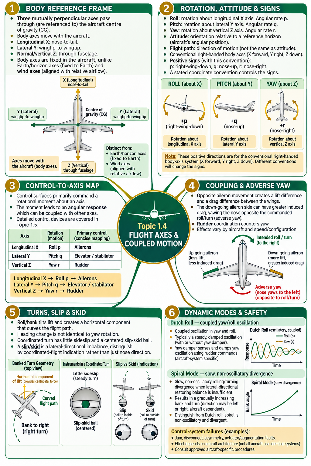
Quick recall
- Longitudinal X → roll p → ailerons.
- Lateral Y → pitch q → elevator / stabilator.
- Vertical Z → yaw r → rudder.
- Attitude is orientation; flight path is direction of motion.
- Adverse yaw is yaw opposite the commanded roll/turn that may arise from aileron drag difference.
- Dutch roll oscillates; spiral instability is a slow non-oscillatory divergence.
Further reading
- NASA Glenn Research Center — Rotation and control axes, for body-axis directions and roll, pitch and yaw.
- NASA — Principles of Flight: Axes / Control Surfaces, with diagrams connecting control surfaces and aircraft motion.
- FAA Pilot’s Handbook — Chapter 5: Aerodynamics of Flight, for lateral-directional stability, Dutch roll and spiral instability.
- FAA Pilot’s Handbook — Chapter 6: Flight Controls and Chapter 8: Flight Instruments, for the conventional control mapping and slip-skid indications.
UPSC-style self assessment
36 questions on Topic 1.4
Use the stated axis convention, separate angular motion from attitude and flight path, and distinguish coupled oscillation from slow divergence. Select one option and open the explanation.
A. Body axes and reference frames
Q01.Which pairing correctly relates an aircraft body axis to rotation about it?
Reveal answer and explanation
Answer A. Roll is rotation about the nose-to-tail longitudinal axis.
Q02.The aircraft’s nose moves up and down through a pitching rotation. About which axis does this rotation occur?
Reveal answer and explanation
Answer C. Pitch is rotation about the lateral, wingtip-to-wingtip body axis.
Q03.In the basic body-axis model, the three reference axes are usually described as intersecting at or being referenced to the aircraft’s:
Reveal answer and explanation
Answer B. The CG is the usual reference origin for aircraft rotation and moments; it is not the same as the aerodynamic centre or geometric centre.
Q04.Which statement best describes body axes during a coordinated turn?
Reveal answer and explanation
Answer D. Body axes are aircraft-fixed. Earth/horizon axes are Earth-referenced; wind axes follow relative airflow.
Q05.Which frame is defined in relation to the relative airflow?
Reveal answer and explanation
Answer A. Wind axes are aligned with the relative airflow; body axes are fixed to the airframe.
Q06.Which rate-symbol sequence corresponds to roll, pitch and yaw, respectively, in standard flight-dynamics notation?
Reveal answer and explanation
Answer B. p, q and r denote body-axis roll, pitch and yaw rates, respectively.
Q07.The lateral body axis of a conventional airplane runs approximately:
Reveal answer and explanation
Answer C. The lateral axis spans the aircraft from side to side and is the axis of pitch rotation.
Q08.Consider the following statements about aircraft axes:
1. The longitudinal axis runs approximately nose to tail.
2. The lateral axis is the axis about which the aircraft pitches.
3. The vertical axis is the axis about which the aircraft rolls.
Which statements are correct?
Reveal answer and explanation
Answer D. Statements 1 and 2 are correct. Roll is about the longitudinal axis, not the vertical axis.
B. Rotation signs, attitude and orientation
Q09.Using X forward, Y right and Z down, a positive roll rate p conventionally means:
Reveal answer and explanation
Answer A. Under this stated right-handed body convention, positive rotation about X is right-wing-down roll.
Q10.With X forward, Y right and Z down, positive pitch rate q corresponds to:
Reveal answer and explanation
Answer D. Positive pitch is conventionally nose-up for the stated body-axis convention.
Q11.Under the same convention, positive yaw rate r means:
Reveal answer and explanation
Answer B. Yaw is rotation about the vertical body axis; positive r is nose-right with the convention stated in the lesson.
Q12.Which statement correctly distinguishes attitude from flight path?
Reveal answer and explanation
Answer C. The nose orientation and the velocity direction can differ during manoeuvres and sideslip.
Q13.Which statement about heading and body yaw rate r is most accurate?
Reveal answer and explanation
Answer A. Heading is an orientation angle; r is an angular rate about the body Z axis. In a general attitude, Euler heading rate and body yaw rate are not identical.
Q14.Why should a question about positive roll, pitch or yaw first be read with its coordinate convention?
Reveal answer and explanation
Answer D. Physical motion is unchanged, but component signs depend on the chosen right-handed coordinate system.
C. Conventional control-to-axis mapping
Q15.In a conventional airplane, ailerons primarily command rotation about the:
Reveal answer and explanation
Answer B. Ailerons create differential wing lift and a rolling moment about the longitudinal axis.
Q16.The conventional primary control for pitch about the lateral axis is the:
Reveal answer and explanation
Answer A. Elevator or all-moving stabilator changes tail force and pitching moment about the lateral axis.
Q17.Rudder input primarily commands yaw about the:
Reveal answer and explanation
Answer C. Rudder side force at the tail produces a yawing moment about the vertical axis.
Q18.Assertion (A): A stabilator can provide pitch control about the lateral axis.
Reason (R): A stabilator is an all-moving horizontal tail surface that changes aerodynamic force and pitching moment.
Reveal answer and explanation
Answer A. The moving horizontal-tail surface changes tail force and the resulting pitch moment about the lateral axis.
Q19.Which sequence best describes how a conventional primary control changes aircraft rotation?
Reveal answer and explanation
Answer B. A surface changes aerodynamic force; the force and its moment arm produce a moment, then angular acceleration and response.
Q20.Which statement about the standard aileron–roll pairing is most accurate?
Reveal answer and explanation
Answer A. Roll is the primary response; aerodynamic coupling can also create adverse yaw. Some designs use spoilers or combined surfaces as well.
D. Coupled motion, turns, slip and skid
Q21.Adverse yaw during aileron input is commonly associated with:
Reveal answer and explanation
Answer C. The lift and drag difference between wings can yaw the nose opposite the commanded roll/turn.
Q22.In a typical conventional aileron pair, which side can experience greater induced drag during the roll command?
Reveal answer and explanation
Answer A. A down-going aileron typically increases local lift and may increase induced drag, producing a yawing tendency.
Q23.Which control combination is commonly used to establish a coordinated conventional airplane turn?
Reveal answer and explanation
Answer D. The control inputs work together; the required coordination depends on aircraft and flight condition.
Q24.For a steady, level coordinated turn, which relationship correctly describes bank angle φ, speed V, turn radius r and load factor n?
Reveal answer and explanation
Answer B. The vertical lift component balances weight and the horizontal component supplies centripetal force. From those components, tan φ = V²/(rg); since n = L/W, n = 1/cos φ. This idealized relation assumes a steady, level coordinated turn.
Q25.What does a centred slip-skid ball indicate in a steady turn?
Reveal answer and explanation
Answer C. The ball is a coordination cue; a centred ball does not mean wings-level flight.
Q26.In a turn, when the inclinometer indicates a slip, the ball moves to the:
Reveal answer and explanation
Answer B. In a slip, the turn rate is too small for the bank angle and the ball moves to the inside; in a skid it moves outside.
Q27.A conventional airplane has excessive yaw into the turn relative to its bank. The likely coordination condition is a:
Reveal answer and explanation
Answer A. Excessive turn rate/yaw for the bank is a skid; confirm coordination using the appropriate instrument indication.
Q28.Which distinction between yaw and heading is correct?
Reveal answer and explanation
Answer B. Yaw describes rotation about an axis; heading describes orientation and can differ from the direction of travel.
Q29.Match each rotation to the axis about which it occurs: 1. Roll 2. Pitch 3. Yaw; a. Lateral Y b. Vertical Z c. Longitudinal X
Rotations
- 1.Roll
- 2.Pitch
- 3.Yaw
Axes
- a.Lateral Y
- b.Vertical Z
- c.Longitudinal X
Reveal answer and explanation
Answer B. Roll is about X, pitch about Y and yaw about Z.
E. Dynamic modes, yaw damping and failures
Q30.Dutch roll is best described as:
Reveal answer and explanation
Answer C. Dutch roll is an oscillatory coupled yaw/roll mode, often also involving sideslip.
Q31.On an aircraft equipped with a conventional yaw-damping function, its principal purpose is to:
Reveal answer and explanation
Answer A. Yaw dampers add damping to yaw oscillations such as Dutch roll on equipped aircraft; implementation varies by system.
Q32.Which response is most characteristic of a spiral instability?
Reveal answer and explanation
Answer D. Spiral divergence is a slow non-oscillatory lateral-directional mode; it is distinct from Dutch roll.
Q33.Which statement best distinguishes Dutch roll from spiral instability and identifies a factor behind the latter?
Reveal answer and explanation
Answer B. Dutch roll is oscillatory; spiral instability is a slow, non-oscillatory divergence. A relative imbalance between directional stability and lateral / dihedral restoring tendency can promote the latter, but the balance is aircraft-dependent.
Q34.A control-surface jam is reported during a safety review. Which conclusion is most defensible without aircraft-specific details?
Reveal answer and explanation
Answer C. Control linkages, actuators, augmentation and aerodynamic coupling vary. Do not infer a universal outcome or response.
Q35.Why can a yaw-damper or actuator failure not be assigned one universal effect across all aircraft?
Reveal answer and explanation
Answer D. Failure symptoms and procedure depend on installed architecture and aircraft-specific approved information.
Q36.A pilot reports a repeated side-to-side yaw oscillation with accompanying wing rocking. Which mode should an investigator consider first?
Reveal answer and explanation
Answer D. Repeated coupled yaw and roll point to Dutch roll; a spiral tendency is slow and non-oscillatory.
Fast recall before practice
Revision tables: all Topic 1.4 concepts
Use these tables to check the frame, sign convention, control mapping, coupling and dynamic-mode distinctions together.
1. Body axes, rotations and rates
| Axis | Direction / frame | Rotation | Rate |
|---|---|---|---|
| Longitudinal X | Nose to tail; body-fixed | Roll | p |
| Lateral Y | Side to side / wingtip-to-wingtip; body-fixed | Pitch | q |
| Normal / vertical Z | Through fuselage; body-fixed | Yaw | r |
2. Reference frames and related terms
| Frame / quantity | Definition | Common confusion |
|---|---|---|
| Body axes | Fixed to and rotate with the aircraft; moments commonly referenced to CG. | Do not treat as Earth-fixed. |
| Earth / horizon axes | Earth-referenced orientation frame. | Bank, pitch attitude and heading are orientations relative to references. |
| Wind axes | Aligned to relative airflow. | May not align with fuselage/body axes. |
| Attitude | Aircraft orientation. | Not necessarily equal to flight-path direction. |
| Flight path | Direction of velocity through the air. | Not necessarily where the nose points. |
| Angle of attack | Angle between a chord reference and relative airflow. | Not pitch attitude. |
| Rates p, q, r | Angular rates about X, Y, Z, respectively. | Not angular positions or linear speed. |
3. Signs for one stated convention
| Positive rate | Positive motion | Negative motion | Convention reminder |
|---|---|---|---|
| p about X | Right wing down | Left wing down | Roll |
| q about Y | Nose up | Nose down | Pitch |
| r about Z | Nose right | Nose left | Yaw |
Sign check: Coordinate conventions can differ. State the axes and use one convention consistently through the question.
4. Conventional primary control mapping
| Control | Primary rotation | Moment axis | Typical cockpit input |
|---|---|---|---|
| Ailerons | Roll p | Longitudinal X | Stick/yoke left-right |
| Elevator / stabilator | Pitch q | Lateral Y | Stick/yoke fore-aft |
| Rudder | Yaw r | Vertical Z | Rudder pedals |
| Control response chain | Input → deflection → force → moment → angular response | Can couple into other axes | Aircraft-specific system |
5. Coupling, adverse yaw and turns
| Concept | What happens | Exam cue |
|---|---|---|
| Coupled motion | One input/disturbance produces responses about more than one axis. | Axes are descriptive; aircraft dynamics interact. |
| Adverse yaw | Aileron-generated lift/drag difference yaws nose opposite commanded roll/turn. | Down-going aileron side may have greater induced drag. |
| Coordinated turn | Banked lift has a horizontal component that curves the flight path; for a steady level turn, tan φ = V²/(rg) and n = 1/cos φ. | At fixed speed, smaller radius requires greater bank; the relation assumes level coordinated flight. |
| Centred ball | Indicates coordinated flight in the inclinometer’s sense. | Does not mean wings level. |
6. Slip versus skid
| Condition | Turn / bank relation | Ball | Typical directional excess |
|---|---|---|---|
| Slip | Turn rate too small for bank | Inside of turn | Insufficient yaw into turn is a common cause |
| Skid | Turn rate too great for bank | Outside of turn | Excessive yaw into turn is a common cause |
| Coordinated | Rate and bank are matched | Centred | Little indicated lateral imbalance |
7. Dutch roll, spiral mode and yaw damper
| Item | Motion / function | Remember |
|---|---|---|
| Dutch roll | Coupled yaw-roll oscillation, commonly with sideslip; the two responses may be out of phase. | Sideslip plus interacting directional and lateral restoring effects; damping varies. |
| Spiral instability | Slow, non-oscillatory bank/turn divergence when unstable. | Can develop when directional stability outweighs lateral / dihedral restoring tendency. |
| Yaw damper | Automatic damping, commonly using rudder commands on equipped aircraft. | Used to reduce yaw oscillation; architecture and failure effects are aircraft-specific. |
| Jam / restriction | May limit or bias a surface’s movement. | Exact effect depends on linkage, surface and flight condition. |
| Disconnect / break | May interrupt the control command path. | Surface position and backup control paths vary. |
| Asymmetry / stuck surface | May create a persistent or unequal aerodynamic moment. | Cross-axis response and controllability are aircraft-specific. |
| Actuator / augmentation fault | May remove, limit or add an unintended command. | Redundancy, control laws and approved procedures differ. |
8. High-frequency exam traps
| Trap | Correction |
|---|---|
| “Roll occurs along the longitudinal axis.” | Roll occurs about the longitudinal axis. |
| “The nose pointing up proves the path is climbing.” | Pitch attitude and flight-path direction can differ. |
| “Positive has the same sign in all frames.” | State the right-handed convention and axis directions. |
| “Aileron input creates only roll.” | Lift/drag asymmetry can couple into yaw. |
| “A turn is just yaw.” | Bank tilts lift; its horizontal component curves the path. |
| “Dutch roll and spiral mode are both oscillations.” | Dutch roll oscillates; spiral instability is a slow non-oscillatory divergence. |
| “All yaw dampers and failure responses are alike.” | System architecture and procedures are aircraft-specific. |
9. Topic outline and question coverage
| Level | Concepts included | Lesson sections / questions |
|---|---|---|
| L1 | Longitudinal, lateral and vertical axes; roll, pitch and yaw. | Sections 1–2; Q1–Q8. |
| L2 | Positive and negative rotations; aircraft attitude and orientation. | Section 2; Q9–Q14. |
| L3 | Relation of ailerons, elevator and rudder to the three axes. | Section 3; Q15–Q20. |
| L4 | Coupled motion, adverse yaw, coordinated turns and slip/skid. | Sections 4–5; Q21–Q29. |
| L5 | Dutch roll, spiral instability, yaw damper and control-system failures. | Section 6; Q30–Q36. |
Revision habit: Draw the aircraft and axes, label the axis of rotation, write the sign convention, then trace the control moment and any coupled response.
10. High-Yield Mnemonics, Examination Traps & Fast Solving Tricks
Memorize these aircraft axes, cross-coupling relationships, and stability mode distinctions for Topic 1.4.
| Mnemonic / Hook | Concept & Pointwise Coordinates | 5-Second Recall Rule |
|---|---|---|
| L-P-Y : R-P-Y : A-E-R |
|
Match axis to motion to primary control surface in 2 seconds flat! |
| STEP ON THE BALL |
|
"Step on the ball" directly centers the ball and restores coordinated, zero-sideslip flight! |
| SLIP IN, SKID OUT |
|
Ball on inside of turn = Slip. Ball on outside of turn = Skid (Skidding turn into stall produces lethal spin!). |
| DUTCH WAGS, SPIRAL DIVES |
|
Wagging wing-rock oscillation = Dutch Roll. Slow continuous bank steepening = Spiral Divergence. |
Examiner Traps & Rapid Elimination Tricks
| Common UPSC Trap | Misconception Statement | Actual Technical Reality | Fast Solving Heuristic |
|---|---|---|---|
| Trap 1: Axis Origin | "The aircraft body axes intersect at the aerodynamic center of the wing." | FALSE. The three mutual perpendicular aircraft body axes (X, Y, Z) ALWAYS intersect at the Center of Gravity (CG) of the complete aircraft. | Origin is always the CG. Any question stating Aerodynamic Center or Cockpit is wrong. |
| Trap 2: Adverse Yaw Direction | "When right aileron is applied to roll right, adverse yaw yaws the nose to the right." | FALSE. To roll right, the left aileron moves DOWN (increasing camber, lift, and induced drag), while right aileron moves UP. The increased induced drag on the left wing pulls the nose to the LEFT (opposite to the commanded roll)! | Adverse yaw always turns the nose OPPOSITE to the direction of roll. Coordinated rudder in the roll direction is required! |
| Trap 3: Dihedral vs Vertical Fin | "Wing dihedral provides directional stability about the vertical axis." | FALSE. Wing dihedral provides lateral (roll) stability (Clβ < 0). Directional (yaw) stability is provided primarily by the vertical stabilizer (fin) (Cnβ > 0). | Dihedral = Roll / Lateral (X). Vertical Fin = Yaw / Directional (Z). |
| Trap 4: Phugoid vs Short Period | "The phugoid mode involves rapid oscillations in angle of attack." | FALSE. The phugoid mode is a long-period (30–100s) exchange between airspeed and altitude at virtually constant angle of attack (Δα ≈ 0). The short-period mode is a rapid (1–3s) oscillation in α and pitch rate. | Constant α + speed/altitude trading = Phugoid. Rapid α oscillation = Short Period. |
UPSC Air Safety Officer Examination Pro-Tips: Lateral-Directional Stability Ratios
- Stability Mode Trade-Off: Strong directional stability (Cnβ) relative to dihedral effect (Clβ) prevents Dutch roll, but makes the aircraft prone to spiral divergence. Conversely, strong dihedral effect relative to directional stability promotes Dutch roll.
- Adverse Yaw Countermeasures: Aircraft designers neutralize adverse yaw via (1) Differential Ailerons (up-going aileron deflects through a larger angle than down-going aileron), (2) Frise Ailerons (leading edge of up-going aileron protrudes below lower wing surface to create drag), and (3) Roll Spoilers.
- Yaw Damper Failure in Swept-Wing Jets: Dispatching with an inoperative yaw damper restricts maximum operating altitude (FL) and speed (MMO) due to Dutch roll excitation risks in high-altitude cruise.