Forces of Flight: Lift, Weight, Thrust and Drag
Build a vector-based understanding of aircraft motion. Learn when forces balance, how climb and glide change their components, and why acceleration depends on the resultant force along the flight path.
1. Begin with the four force resultants
A useful first model replaces distributed aerodynamic and gravitational forces with four resultant vectors. It predicts translation; a complete aircraft model also considers moments, rotation and control response.

| Force | Symbol and usual direction | What to remember |
|---|---|---|
| Lift | L; perpendicular to relative airflow / flight path in the simple model. | Mostly generated by wings; it is not automatically “straight up.” |
| Weight | W = mg; toward Earth through the centre of gravity. | Gravity acts during climb, descent and turns too. |
| Thrust | T; generally forward, approximately along the path in basic cases. | Produced by propulsion; its line of action can be angled or vectored. |
| Drag | D; opposite motion relative to the air. | It opposes air-relative motion, not necessarily ground track. |
Direction check: Lift and drag are aerodynamic resultants defined relative to airflow. Weight remains Earth-directed. Thrust direction depends on the propulsion installation.
2. Apply Newton’s three laws and test equilibrium
For translational motion, Newton’s second law is ΣF = ma. Add force vectors, not just magnitudes. If the resultant force is zero, acceleration is zero and velocity is constant; that velocity can be nonzero.
| Law | Rule | Aircraft application and exam check |
|---|---|---|
| First — inertia | If the resultant external force is zero, an object remains at rest or moves with constant velocity in an inertial frame. | “Constant velocity” means both speed and direction stay fixed; a turning aircraft is accelerating even at constant speed. |
| Second — resultant force | ΣF = ma; resolve the vector equation along chosen axes. | The along-path and normal components explain speeding up, slowing down, climbing and turning. |
| Third — action and reaction | If body A exerts a force on body B, body B exerts an equal and opposite force on A. | The pair acts on different bodies, so it does not cancel on one aircraft free-body diagram. A propeller accelerates air aft; the air exerts forward thrust on the propeller and aircraft. A wing turns airflow and experiences the corresponding aerodynamic reaction. |
| Term | Meaning | What it does not guarantee |
|---|---|---|
| Equilibrium of forces | The vector resultant force is zero. | It does not mean the aircraft is stationary or level. |
| Unaccelerated motion | Velocity is constant in magnitude and direction. | It can be a steady climb or descent. |
| Constant speed | Speed magnitude stays fixed. | Direction may change in a turn; centripetal acceleration is then present. |
For straight-and-level, unaccelerated flight in the simple model, vertical and longitudinal components balance separately: L = W and T = D. Equality of one pair balances only that component. A steady attitude also requires relevant moments about the centre of gravity to balance; the equations here focus on translational forces.
3. Straight-and-level flight: the reference case
For straight, level flight at constant speed, flight-path angle γ is zero and acceleration is zero. The force components reduce to two opposing pairs:
- Vertical: L − W = 0, so L = W.
- Along the path: T − D = 0, so T = D.
| Change | Immediate tendency in the simple model | Caution |
|---|---|---|
| T > D | Forward acceleration. | It does not by itself mean the aircraft climbs. |
| T < D | Deceleration along the path. | The aircraft may continue flying while slowing or changing path. |
| L > W | Upward acceleration when the path is level. | Actual motion depends on every force component. |
| L < W | Downward acceleration in that same level-path model. | A steady straight climb can have L < W. |
Attitude is not flight path. Pitch attitude describes aircraft orientation; γ describes velocity direction relative to the horizon. Angle of attack is a third angle.
4. Resolve forces along climb, descent or curve
For motion in a vertical plane, choose axes parallel and perpendicular to the flight path. Let γ be positive for a climb, V speed along the path, and R its radius of curvature. In the basic model, thrust acts along the path and lift is normal to it.
Along path: T − D − W sin γ = m dV/dt
Normal to path: L − W cos γ = mV2/R
For a straight path, R tends to infinity and normal acceleration is zero. If speed is also constant, the equations reduce to T − D = W sin γ and L = W cos γ.
| Path | Sign of γ | Steady-speed interpretation |
|---|---|---|
| Level | 0° | T = D; L = W. |
| Climb | Positive | T > D; L = W cos γ < W. |
| Descent | Negative | T − D is negative in a steady straight descent with this convention. |
Angle convention matters: State that climb is positive before assigning signs. L < W alone does not prove descent; a steady straight climb has L = W cos γ.
5. Connect excess thrust, power and glide
Worked example: a steady climb
An aircraft climbs straight at constant speed through γ = 10° and weighs 24 kN. Use sin 10° ≈ 0.174 and cos 10° ≈ 0.985:
- Required excess thrust: T − D = W sin γ ≈ 24 × 0.174 = 4.18 kN.
- Lift for zero normal acceleration: L = W cos γ ≈ 24 × 0.985 = 23.64 kN.
Lift and thrust components together support the climb; lift need not exceed weight in this case.
Excess power and rate of climb
At steady speed, excess power available over that required for level flight supplies the rate of gain of potential energy:
Rate of climb ≈ (Pavailable − Prequired) / W
Watts divided by newtons gives metres per second. If speed is changing, excess power also changes kinetic energy and this simple relation is incomplete.
Glide with no engine thrust
For an ideal steady straight glide, T = 0. With downward glide-angle magnitude |γ|, D = W sin |γ| and L = W cos |γ|. Thus L/D = cot |γ|: a larger lift-to-drag ratio gives a shallower glide in this simplified model.

Compare partial thrust loss, total power loss and engine-out flight
“Thrust loss” does not always mean T = 0. Identify what propulsion remains, then apply the along-path force balance.
| Case | Force/performance model | What follows |
|---|---|---|
| Partial thrust reduction | If the aircraft is initially level and available thrust falls below drag, Tavailable − D < 0. | It begins to decelerate if it holds the same path. Lift does not vanish instantly; speed and flight path then evolve together. |
| Complete power loss, single-engine aircraft | Use the ideal glide model with T = 0; gravity’s along-path component balances drag in a steady glide. | Glide angle and still-air range depend on lift-to-drag ratio. This is a performance model, not an emergency procedure. |
| One engine inoperative (OEI), multi-engine aircraft | Remaining thrust may be positive, while asymmetric thrust and configuration-specific drag affect the result. | Do not assume half the engines means half the climb performance. Weight, density altitude, temperature, configuration and remaining-engine performance matter; use that aircraft’s approved OEI data. |
For an ideal, still-air glide from height h above the landing area, horizontal distance is approximately h(L/D). For example, h = 2.5 km and L/D = 12 give an idealized range of about 30 km. Wind, turns, speed, configuration and terrain change the reachable area, so this estimate is not a planning or operating instruction.
Safety boundary: These relations explain the physics. Actual engine-failure response, glide speed and landing choice follow the aircraft’s approved flight manual and trained procedures.
6. Constant speed can still require a net force
In a coordinated level turn, speed and altitude may stay constant while velocity direction changes. The banked lift vector has a vertical component that balances weight and a horizontal component that supplies centripetal force.
L cos φ = W; L sin φ = mV2/R
Load factor: n = L/W = 1/cos φ (coordinated, level turn)
At 60° bank, cos 60° = 0.5, so n = 2: lift magnitude is twice weight in this idealized steady turn. Direction changes, so acceleration is present even though speed is constant.
Manoeuvre loading beyond the steady turn
Load factor n compares aerodynamic lift with aircraft weight and is commonly expressed as a multiple of g. Turns are one source; a pull-up also needs additional upward force to curve the flight path. At the bottom of an ideal vertical pull-up, with negligible tangential acceleration, L − W = mV2/R, so n = 1 + V2/(gR). A faster pull-up or a tighter radius therefore raises the load.
Accelerated stall-speed relation: Vs,n ≈ Vs,1g√n (same weight and configuration, simplified positive-load case)
At n = 2, stall speed is about 1.41 times its 1g value.
Gusts and other manoeuvres can also change load. Aircraft structural load limits are type-specific; do not infer an allowable limit from these equations. Use the approved flight manual and operate within its limitations.
Apply the model to a safety review
When an occurrence report says “level and steady,” check whether it means constant altitude, speed and straight path; these are separate conditions. A turn, gust or speed change can leave a nonzero resultant force.
2018 PYQ lens — Q7: The item treats T > D as acceleration, not deceleration. Its equilibrium wording is a simplified exam model: full force balance also needs vertical or flight-path-normal balance. “Weight greater than lift” indicates a downward resultant only under its simple force assumptions; inspect the trajectory and all components.
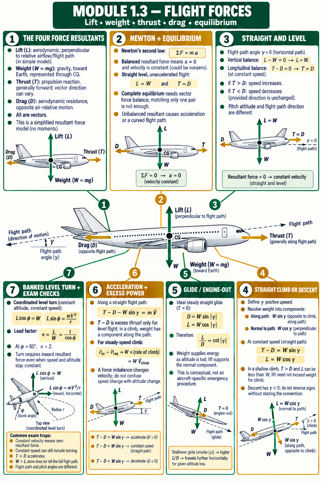
Connect the equations: Topic 1.3 mind map
Move from each force’s direction to the motion equation for level flight, climb, glide and a turn. The assumptions beside each relationship are part of the answer.
Quick recall
1. What conditions give straight-level, unaccelerated flight in the simple model?
Answer: L = W and T = D.
2. Does constant speed always mean zero acceleration?
Answer: No. Direction can change in a turn, so velocity changes and centripetal acceleration is present.
3. In a steady straight climb, must lift exceed weight?
Answer: No. L = W cos γ for this model; thrust supplies the along-path weight component.
4. Which way does weight point in a descent?
Answer: Toward Earth, regardless of aircraft attitude or path.
5. What balances drag in an ideal steady glide?
Answer: The component of weight along the glide path; thrust is zero.
6. Why do a propeller’s action and reaction not cancel on the aircraft?
Answer: The propeller acts on the air and the air acts on the propeller/aircraft. The two forces act on different bodies.
Further reading
These primary references explain the force vectors and flight-path components used here. FAA material is supplementary educational guidance; use current DGCA rules and aircraft-approved procedures in Indian operations.
- NASA Glenn Research Center — Forces on an Airplane, including the four force resultants and their usual directions.
- NASA Glenn Research Center — Vector Force Balance for a Glider, showing force components on an ideal glide path.
- NASA Glenn Research Center — Newton’s Laws of Motion, including aircraft examples of action and reaction.
- NASA Glenn Research Center — Forces in a Climb, resolving vectors with Newton’s second law.
- FAA Pilot’s Handbook of Aeronautical Knowledge, Chapter 5: Aerodynamics of Flight.
- FAA Airplane Flying Handbook — Chapter 5: Ground and Flight Maneuvers, including load factor and stall-speed effects in turns.
- UPSC ASO 2018 question paper, Q7 on forces acting on an airplane in flight.
UPSC-style self assessment
37 questions on Topic 1.3
Choose one option, then open the explanation. The set includes the 2018 PYQ, statement questions, matching, assertion–reason, calculations, Newton’s laws, manoeuvre loads and engine-out performance.
A. Forces, vectors and equilibrium
Q01 · 2018 PYQConsider the following statements regarding forces acting on an airplane in flight:
1. Thrust, drag, lift and weight are the forces on an airplane in flight.
2. The airplane is said to be in a state of equilibrium when thrust and drag are equal and opposite.
3. If weight is greater than lift, the airplane will sink.
4. If thrust is greater than drag, the airplane will decelerate.
Which of the above statements are correct?
Reveal answer and explanation
Answer A. The first three are accepted in the paper’s simplified force model. Statement 4 reverses Newton’s second law: excess thrust causes forward acceleration. For a complete vector balance, both longitudinal and vertical (or flight-path-normal) components must balance; statement 2 names only the thrust–drag pair.
Q02.In straight-and-level flight at constant speed, which set of force relationships applies in the basic airplane model?
Reveal answer and explanation
Answer A. With no acceleration and a level straight path, lift balances weight and thrust balances drag.
Q03.A resultant force of zero on an aircraft means that its:
Reveal answer and explanation
Answer B. Newton’s second law gives zero acceleration. Velocity is therefore constant in magnitude and direction; the aircraft can be moving.
Q04.If thrust exceeds drag while the aircraft continues in the same straight direction, the along-path tendency is to:
Reveal answer and explanation
Answer B. The net along-path force is positive, so speed increases if the path direction is unchanged.
Q05.Which statement best describes drag in the basic flight-force model?
Reveal answer and explanation
Answer B. Drag is aerodynamic resistance and opposes air-relative motion; it is not defined as opposite gravity.
Q06.Which force remains directed toward Earth when an aircraft enters a climb or a turn?
Reveal answer and explanation
Answer C. Weight is gravitational and points toward Earth regardless of aircraft attitude or flight path.
Q07.In the elementary model, lift is usually defined as acting:
Reveal answer and explanation
Answer A. Lift is normal to the relative airflow in the simple model; during a climb or bank it is not generally vertical.
Q08.An aircraft maintains constant speed in a coordinated turn. Which statement is correct?
Reveal answer and explanation
Answer B. Velocity includes direction. A turn changes direction and therefore has centripetal acceleration even at constant speed.
B. Flight paths and force resolution
Q09.Let climb angle γ be positive upward. In a straight climb, the component of weight along the path acts:
Reveal answer and explanation
Answer B. For positive climb angle, gravity has a component down the path opposite the climb, equal in magnitude to W sin γ.
Q10.For a straight, constant-speed climb with thrust aligned to the flight path, which pair is correct?
Reveal answer and explanation
Answer A. Resolve weight along and normal to the straight path. Constant speed balances the along-path component; zero normal acceleration balances the normal component.
Q11.For the straight, constant-speed climb in Q10, why is lift less than weight when γ is positive?
Reveal answer and explanation
Answer B. The lift component normal to the path balances W cos γ; thrust’s vertical component helps support the climb.
Q12.For a straight, constant-speed descent with climb-positive γ (< 0) and thrust along the path, the along-path equation implies:
Reveal answer and explanation
Answer A. The stated convention makes γ negative in descent, so W sin γ and T − D are negative in this steady case.
Q13.A steady ideal glide has T = 0. Which force component balances drag along a straight glide path?
Reveal answer and explanation
Answer A. In a steady glide, the weight component down the path balances drag; lift balances the normal component.
Q14.In a straight flight path with radius of curvature R tending to infinity, the normal acceleration term V2/R tends to:
Reveal answer and explanation
Answer B. A straight path has no curvature, so its normal acceleration is zero in this model.
Q15.At constant speed on a straight path, a climb angle of 5° requires what excess thrust for an aircraft weighing 30 kN? Use sin 5° ≈ 0.087.
Reveal answer and explanation
Answer B. T − D = W sin γ = 30 × 0.087 ≈ 2.61 kN.
Q16.For Q15’s straight, constant-speed climb, estimate lift using cos 5° ≈ 0.996.
Reveal answer and explanation
Answer A. L = W cos γ = 30 × 0.996 = 29.88 kN.
C. Calculations and performance applications
Q17.A 2,000 kg aircraft flies straight and level. Thrust is 10 kN and drag is 6 kN. What is its initial along-path acceleration?
Reveal answer and explanation
Answer B. Net thrust = 4,000 N; a = F/m = 4,000/2,000 = 2 m/s². The question asks for the initial along-path acceleration.
Q18.An aircraft has excess power of 720 kW and weight of 24 kN. Under the steady-speed climb approximation, its rate of climb is:
Reveal answer and explanation
Answer B. Rate of climb ≈ excess power/weight = 720,000/24,000 = 30 m/s.
Q19.An ideal steady glide has L/D = 12. Its glide angle magnitude is closest to:
Reveal answer and explanation
Answer A. For the simple steady glide, L/D = cot |γ|, so tan |γ| = 1/12 and |γ| ≈ 4.8°.
Q20.Fuel is consumed during straight, level flight. If speed, altitude and configuration are momentarily unchanged, which adjustment to required lift follows from L = W?
Reveal answer and explanation
Answer B. In level unaccelerated flight lift equals current weight. Consuming fuel reduces weight, so required lift decreases under the stated conditions.
Q21.In a coordinated level turn at 60° bank, the ideal load factor is:
Reveal answer and explanation
Answer C. n = 1/cos 60° = 2 for a coordinated level turn.
Q22.A straight, constant-speed climb is at 10° with weight 24 kN. Which approximate pair is correct? Use sin 10° = 0.174 and cos 10° = 0.985.
Reveal answer and explanation
Answer A. T − D = 24 sin 10° ≈ 4.18 kN; L = 24 cos 10° ≈ 23.64 kN.
Q23.Which statement about angle of attack and flight-path angle is correct?
Reveal answer and explanation
Answer B. Pitch attitude describes aircraft orientation; flight-path angle describes velocity direction. Angle of attack is between a chosen aircraft reference line and relative airflow.
D. Statements, matching and safety reasoning
Q24.Assertion (A): An aircraft can maintain constant speed in a turn while still accelerating.
Reason (R): The direction of its velocity changes during the turn.
Choose the correct relationship.
Reveal answer and explanation
Answer A. Acceleration is the rate of change of velocity, including direction; the changing direction requires an inward resultant force.
Q25.Consider these statements about the four forces:
1. Weight points toward Earth.
2. Drag opposes air-relative motion.
3. Lift is always vertical.
Which statements are correct?
Reveal answer and explanation
Answer B. Weight is Earth-directed and drag opposes relative motion. Lift is normal to relative airflow in the simple model, so it is not always vertical.
Q26.Match each force to its primary source or direction:
1. Lift 2. Weight 3. Thrust 4. Drag
a. Propulsion-system reaction b. Gravity c. Aerodynamic force normal to airflow d. Resistance opposite air-relative motion
Reveal answer and explanation
Answer A. Lift is aerodynamic and normal to airflow; weight is gravity; thrust is produced by propulsion; drag resists air-relative motion.
Q27.A pilot reports “constant speed.” Which additional conclusion is justified without more information?
Reveal answer and explanation
Answer C. Speed omits velocity direction and altitude; a constant-speed turn still needs centripetal acceleration.
Q28.In a coordinated level turn, which statement is correct when speed is constant?
Reveal answer and explanation
Answer B. In a steady level turn, thrust and drag can balance along the path, while the horizontal lift component supplies centripetal force and the vertical component balances weight.
Q29.After a hypothetical engine power loss, which is the soundest first-principles statement about a glide?
Reveal answer and explanation
Answer B. An unpowered aircraft can glide; the ideal force components are D = W sin |γ| and L = W cos |γ|. This is not an emergency checklist.
Q30.An aircraft is in a straight, constant-speed 8° climb. An observer argues, “Lift is less than weight, therefore the aircraft must be descending.” What is the best correction?
Reveal answer and explanation
Answer B. For a steady straight climb, L = W cos γ and T − D = W sin γ. The initial claim ignores the thrust and path components.
E. Coverage extensions: Newton’s laws, manoeuvre loading and engine-out performance
Q31.Which pair correctly illustrates Newton’s third law for a propeller-driven aircraft?
Reveal answer and explanation
Answer B. The propeller’s force on the air and the air’s force on the propeller are equal and opposite, but they act on different bodies. They do not cancel on the aircraft’s free-body diagram.
Q32.In an ideal coordinated level turn at a bank angle of 45°, what is the load factor closest to?
Reveal answer and explanation
Answer C. For a coordinated level turn, n = 1/cos φ. Thus n = 1/cos 45° = √2 ≈ 1.41.
Q33.An aircraft’s 1g stall speed is 80 kt. In the same configuration and at the same weight, estimate the stall speed at load factor n = 2.
Reveal answer and explanation
Answer B. Under the simplified same-weight, same-configuration relation, Vs,n = Vs,1g√n = 80√2 ≈ 113 kt.
Q34.At the bottom of an ideal vertical pull-up, take V = 90 m/s, R = 900 m and g ≈ 10 m/s². Estimate the load factor.
Reveal answer and explanation
Answer B. At the bottom, L − W = mV2/R, so n = L/W = 1 + V2/(gR) = 1 + 8100/9000 = 1.9.
Q35.During initially straight-and-level flight, available thrust suddenly falls below drag but remains positive. What is the immediate first-principles tendency if the path is momentarily unchanged?
Reveal answer and explanation
Answer A. With a temporarily unchanged level path, Tavailable − D < 0 gives negative along-path acceleration. A later speed or path change requires a new force balance; partial thrust loss is not the same as T = 0.
Q36.In an ideal still-air glide, an aircraft is 2.5 km above a landing area and has L/D = 12. Estimate the horizontal distance in the simplified model.
Reveal answer and explanation
Answer C. Ideal still-air horizontal distance is approximately height × glide ratio: 2.5 × 12 = 30 km. Wind, turns, configuration, speed and terrain change real-world reach.
Q37.A twin-engine aircraft loses one engine. Which statement about its remaining climb performance is soundest?
Reveal answer and explanation
Answer D. Loss of one engine changes excess thrust/power and can add asymmetric drag and control demands. The result is aircraft-specific and must not be inferred by simply halving the former climb rate.
Fast recall before practice
Revision tables: all Topic 1.3 concepts
Read the stated conditions with every equation. The same force can have different components when the path or axes change.
1. Four forces and directions
| Force | Source / symbol | Usual direction in the basic model | Exam check |
|---|---|---|---|
| Lift | Aerodynamic resultant; L | Normal to relative airflow / flight path | Not always vertical; depends on path and bank. |
| Weight | Gravity; W = mg | Toward Earth through CG | Direction is Earth-fixed in the model. |
| Thrust | Propulsion resultant; T | Generally forward | May be inclined or vectored; resolve it if not path-aligned. |
| Drag | Aerodynamic resistance; D | Opposes air-relative motion | Do not confuse ground track with relative airflow. |
2. Motion, balance and acceleration
| Idea | Relationship | Interpretation |
|---|---|---|
| First law — inertia | ΣF = 0 ⇒ velocity is constant | Rest or uniform straight-line motion persists in an inertial frame. |
| Vector equation | ΣF = ma | Use components in a chosen axis system. |
| Third law — action/reaction | FA on B = −FB on A | Equal and opposite forces act on different bodies; they do not cancel on one aircraft free-body diagram. |
| Zero resultant | ΣF = 0 ⇒ a = 0 | Velocity is constant; it need not be zero. |
| Straight-level, unaccelerated | L = W; T = D | Vertical and longitudinal force pairs balance. |
| Excess thrust in level path | T > D ⇒ positive along-path acceleration | Speed increases if path direction is unchanged. |
| Constant-speed turn | Velocity direction changes ⇒ a ≠ 0 | Centripetal force remains even though speed magnitude is constant. |
3. Flight-path equations and assumptions
| Component / case | Equation | Condition or use |
|---|---|---|
| Along path | T − D − W sin γ = m dV/dt | General straight flight-path component in the simplified model. |
| Normal to path | L − W cos γ = mV2/R | For a curved path of radius R; straight path gives zero normal acceleration. |
| Steady straight path | T − D = W sin γ; L = W cos γ | Constant speed, no path curvature, thrust aligned with path. |
| Level path | γ = 0; at constant speed T = D, L = W | Special case of the steady straight-path equations. |
| Ideal steady glide | T = 0; D = W sin |γ|; L = W cos |γ| | Thrust absent; weight component along path supplies the energy lost with altitude. |
4. Climb, glide and turning relationships
| Quantity | Relationship | Assumptions / meaning |
|---|---|---|
| Excess thrust in climb | T − D = W sin γ | Straight climb at constant speed, thrust along path. |
| Lift in climb | L = W cos γ | Same case, no normal acceleration; lift can be less than weight. |
| Rate of climb | ROC ≈ (Pavailable − Prequired)/W | Steady-speed climb; watts/newtons yields m/s. |
| Glide ratio | L/D = cot |γ| | Ideal steady straight glide; larger L/D means shallower path. |
| Level coordinated turn | L cos φ = W; n = 1/cos φ | Vertical lift component balances weight; horizontal component turns aircraft. |
| 60° bank | n = 2 | Ideal level coordinated turn; lift magnitude is twice weight. |
| Pull-up at bottom of vertical curve | n = 1 + V2/(gR) | Assumes negligible tangential acceleration; greater speed or tighter radius increases load. |
| Stall speed at positive load factor | Vs,n ≈ Vs,1g√n | Simplified relation at the same weight and configuration; at n = 2, stall speed is about 1.41 times the 1g value. |
| Structural load limit | Aircraft-specific approved limit | Do not infer a generic allowable n; follow the aircraft’s approved limitations. |
| Ideal still-air glide range | Horizontal distance ≈ height × L/D | Only an ideal estimate; wind, turns, configuration, speed and terrain alter reach. |
5. Common exam traps and corrections
| Trap | Correction |
|---|---|
| “Constant speed means no acceleration.” | Only if direction is constant too; a turn changes velocity direction. |
| “Lift is always vertical.” | In the basic model lift is perpendicular to relative airflow / flight path. |
| “Lift must exceed weight for climb.” | In a steady straight climb, L = W cos γ while thrust provides an along-path component. |
| “T > D makes the aircraft climb.” | It produces along-path acceleration in level flight; climb depends on the full force balance and flight path. |
| “Equal thrust and drag alone prove equilibrium.” | That balances only the longitudinal pair; other force components and moments still matter. |
| “Newton’s third-law forces cancel on the aircraft.” | The pair acts on two different bodies, such as propeller/air and air/propeller. |
| “The 1g stall speed is unchanged in a manoeuvre.” | At the same weight and configuration, the simplified accelerated-stall relation is Vs,n ≈ Vs,1g√n. |
| “Engine failure means the aircraft immediately stops flying.” | An aircraft can glide; operational actions and speeds must follow approved procedures. |
| “One engine lost means exactly half the climb rate.” | Engine-out performance depends on remaining thrust, drag/asymmetry and aircraft conditions; use approved OEI data. |
| “Pitch attitude is the flight-path angle.” | Aircraft orientation and velocity direction are different; angle of attack is different again. |
6. Topic outline and question coverage
| Level | Concepts included | Lesson / questions |
|---|---|---|
| L1 | Lift, drag, thrust, weight, force balance and simple imbalance effects. | Sections 1–3; Q1–Q8, Q25–Q28. |
| L2 | Newton’s first, second and third laws; steady/unsteady flight; force directions and flight-path geometry. | Sections 2–4; Q3, Q7–Q14, Q23–Q27, Q31. |
| L3 | Straight-level flight, climb, descent, acceleration and deceleration. | Sections 3–5; Q4, Q9–Q18, Q22, Q30. |
| L4 | Banked turns, load factor, pull-up loading, accelerated stall-speed effects, aircraft-specific structural limits, excess thrust and excess power. | Sections 5–6; Q8, Q18, Q21, Q24, Q28, Q32–Q34. |
| L5 | Partial versus total thrust loss, ideal glide angle and range, OEI performance factors and aircraft-specific flight-path safety boundaries. | Section 5; Q13, Q19, Q29, Q35–Q37. |
| PYQ audit | UPSC ASO 2018 Q7: four forces, equilibrium wording, weight/lift and thrust/drag statements. | Tagged as Q1; expected option A in the paper’s simplified model, with the vector-balance caveat explained. |
Revision habit: Sketch the path and arrows first. Then state the axis, sign convention, acceleration condition and assumptions before substituting numbers.
7. High-Yield Mnemonics, Examination Traps & Fast Solving Tricks
Master these equilibrium relationships, bank-angle load factors, and rapid calculation shortcuts for Topic 1.3.
| Mnemonic / Hook | Concept & Pointwise Formula | 5-Second Solving Rule |
|---|---|---|
| CLIMB: LIFT IS LESS! |
|
In steady climb: L < W. Never choose "L > W" for a steady climb; extra Thrust drives the climb, NOT extra Lift! |
| 60° BANK = 2G (DOUBLE WEIGHT) |
|
Bank at 60° &implies; n = 2.0g &implies; Vstall increases by 41%! Bank at 45° &implies; n = 1.41g &implies; Vstall increases by 19%! |
| WEIGHT DOES NOT SHORTEN GLIDE |
|
Heavier aircraft glides at a higher true airspeed, reaching the ground sooner, but covers the exact same footprint! |
| LIFT IS NORMAL TO THE WIND |
|
Lift is relative to air velocity vector. Weight is relative to gravity / Earth center. |
Examiner Traps & Rapid Elimination Tricks
| Common UPSC Trap | Misconception Statement | Actual Technical Reality | Fast Solving Heuristic |
|---|---|---|---|
| Trap 1: Equilibrium = Zero Speed | "An aircraft in flight equilibrium must have zero velocity." | FALSE. Equilibrium means zero acceleration (∑ F = 0, a = 0). An aircraft in straight, level, unaccelerated flight at 450 knots is in complete translational equilibrium! | Equilibrium &implies; Constant velocity (a = 0). Does NOT mean stationary! |
| Trap 2: Pull-up vs Steady Climb | "Lift must exceed weight during the entire climb to cruising altitude." | FALSE. L > W is required ONLY for the brief curved entry transition (pitch-up). Once the climb angle γ is established and velocity is steady, L = W cosγ < W. | Curving the flight path upwards requires L > W. Steady climb requires L < W and T > D! |
| Trap 3: Centripetal Force Source | "In a coordinated turn, the rudder provides the horizontal force that turns the airplane." | FALSE. The horizontal component of lift (L sinφ = (mV2)/R) provides 100% of the centripetal force required to curve the flight path. The rudder simply maintains directional trim (zero sideslip). | Turning force comes from the Wing (Lift vector tilt), NEVER from the rudder! |
| Trap 4: Wind Effect on Max Glide Ratio | "A tailwind increases the aircraft's aerodynamic L/D ratio." | FALSE. Wind cannot alter aerodynamic L/D (which depends solely on angle of attack and airframe geometry). A tailwind increases the ground distance covered by boosting groundspeed, but the airframe's aerodynamic glide ratio remains identical. | Airframe aerodynamic performance (L/D) is independent of ambient wind! |
UPSC Air Safety Officer Examination Pro-Tips: Numerical Rule-of-Thumbs
- Turn Radius Shortcut: R = V2 / (g tanφ). Doubling airspeed V quadruples the turn radius (R ∝ V2). High-speed jet holding patterns require vast airspace!
- Rate of Turn (ω): ω = (g tanφ) / V. For a given bank angle, doubling airspeed cuts the rate of turn in half.
- Load Factor in Steep Turns: n = 1 / cosφ. Notice how rapidly load factor spikes beyond 60°: at 70°, n = 2.92g; at 75°, n = 3.86g; at 80°, n = 5.76g (structural failure hazard!).