Aircraft Parts: Wing, Fuselage, Tail and Empennage
Learn to identify the major airframe parts, explain what each does, and follow how aerodynamic and ground loads pass through the structure. Keep the conventional-airplane diagram in view, while remembering that real aircraft configurations can differ.
1. Start with the whole aircraft
Use this labeled NASA drawing to orient yourself before studying each component. It shows a representative airliner; the exact location, shape and presence of components vary across aircraft designs.

| Part | Primary role |
|---|---|
| Fuselage | Houses crew, passengers, cargo or equipment and joins major aircraft structures. |
| Wing | Produces most of an airplane’s lift and carries fuel or systems on many designs. |
| Empennage | Tail assembly whose surfaces contribute to stability, trim and control. |
| Propulsion installation | Engine, propeller or other installed system provides thrust; mounting structure transmits loads. |
| Landing gear | Supports the aircraft on the ground and transmits taxi, take-off and landing loads. |
Exam rule: A component’s location can suggest its role, but function is the reliable identifier. A stabilizer is not the same thing as its hinged control surface.
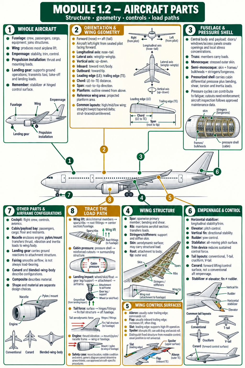
Connect the parts: Topic 1.2 mind map
Use the branches to connect each aircraft part with its purpose, construction terms and safety-relevant load path.
2. Describe position and direction precisely
Aircraft-relative directions
Forward / nose points toward the aircraft’s front; aft / rear points toward its tail. The aircraft’s left and right are determined from the pilot’s seated position facing forward, not from a person looking at the aircraft from outside.
The body reference axes are commonly described as: longitudinal (nose to tail), lateral (side to side, approximately wingtip to wingtip), and vertical (up and down through the aircraft). Axis sign conventions can vary by text; check the stated convention before interpreting a positive direction.
| Term | Meaning | Use it for |
|---|---|---|
| Nose / forward | Front end of the aircraft. | Forward fuselage, cockpit, nose gear. |
| Aft / tail | Direction toward the rear of the aircraft. | Aft fuselage, tail cone, empennage. |
| Inboard / outboard | Toward / away from the aircraft centreline. | Comparing a flap near the body with an aileron near a wingtip. |
| Wing root / wingtip | Inner wing junction / outer end of the wing. | Describing spanwise position and wing structure. |
| Leading / trailing edge | Forward / aft edge of a wing or tail surface in its design reference orientation. | Locating high-lift devices and control surfaces. |
3. Fuselage: the aircraft’s central body
Function and arrangement
The fuselage is the main body structure. Depending on the aircraft, it accommodates the cockpit, crew, passengers, cargo, equipment and systems. It also provides structural interfaces for the wing, empennage, landing gear and propulsion installation. Not every aircraft carries every payload in the fuselage, and some configurations do not have a conventional tube-shaped body.
Windows, doors, hatches, access panels, floor beams, frames and systems penetrations interrupt or shape the shell. These openings need suitable local reinforcement and load transfer. The fuselage may also serve as a cabin pressure boundary on a pressurized aircraft; an unpressurized fuselage still carries structural and operational loads.
Three introductory fuselage construction ideas
| Arrangement | How it works | Recall cue |
|---|---|---|
| Truss | A framework of members carries loads; fabric or a light skin may provide the outer covering on some designs. | Think framework and member forces. |
| Monocoque | The stressed outer skin carries a substantial share of the structural load. | “Shell” does significant structural work. |
| Semi-monocoque | Stressed skin works together with internal members such as frames, bulkheads, stringers and longerons. | Skin plus supporting framework. |
Terminology care: These are idealized construction descriptions. Actual designs may use mixed materials and structural arrangements; do not classify a specific aircraft solely from its appearance.
Pressurized fuselage and local structure
On a pressurized aircraft, the fuselage pressure shell contains the cabin’s differential pressure while also responding to bending, shear, torsion, inertia and aerodynamic loads. Doors and windows create local discontinuities, so the surrounding structure distributes loads around their cutouts. Pressurization cycles are relevant to fatigue, but the inspection method and intervals come from the approved design and maintenance programme.
4. Wing: lifting surface and structural assembly
Wing geometry words
The wing root is the inboard region where the wing joins the fuselage; the wingtip is its outer end. The leading edge meets the airflow first in the design’s forward orientation; the trailing edge is behind it. A local chord is the straight-line distance between the leading and trailing edges at a spanwise station. The distance from one wingtip to the other is the span; the wing’s top-view outline is its planform.
A wing can be high-, mid- or low-mounted relative to the fuselage. It may be strut-braced or cantilevered. Swept, straight, tapered, delta and other planforms describe geometry or arrangement; none changes the basic meaning of “wing root” or “wingtip.” Wing reference area is a projected planform area, rather than the combined area of the upper and lower skin surfaces.

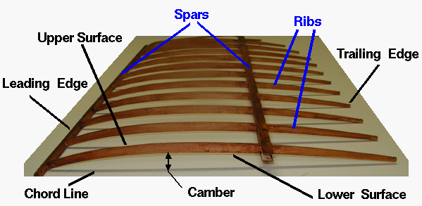
Inside the wing: primary structural members
| Member | Typical contribution | Common confusion |
|---|---|---|
| Spar | Main spanwise structural member; spars and their connections carry important bending and shear loads. | Not the same as a rib; spar direction is broadly root to tip. |
| Rib | Maintains the wing section shape and transfers loads between skin and principal members. | Not the main lengthwise member. |
| Stringer / stiffener | Supports and stiffens the skin, helping it carry structural loads while resisting local deformation. | May run spanwise or chordwise depending on design; check the drawing. |
| Skin | Forms the aerodynamic surface and, in stressed-skin construction, shares structural loads. | Not merely a non-structural cover on every aircraft. |
| Wing attachment | Transfers wing loads into the fuselage or centre section through the designed joint and fittings. | The attachment is part of the load path, not a decorative fairing. |
How the wing joins the fuselage
The wing–fuselage junction is a structural interface. Aerodynamic lift and wing inertia loads pass through the wing skin and internal members into attachments and the centre section, then into the fuselage. The exact arrangement depends on the aircraft; a fairing can cover a joint without being the primary load-carrying member.
| Arrangement | Typical structural idea | Safety-review focus |
|---|---|---|
| Cantilever wing | No external wing strut supports it; internal spars, skin and root/centre-section structure carry the loads. | Follow the wing-root fittings and carry-through structure into the body. |
| Strut-braced wing | A strut forms an additional external load path between the wing and fuselage; the wing and strut work with their attachments. | Inspect the strut, end fittings and connected structure using type-specific instructions. |
| Centre wing box / carry-through | On some designs, a centre section or box connects the wing halves and transfers loads across or through the fuselage structure. | Identify which spars, fittings, frames or bulkheads participate; layouts differ by design. |
| High-, mid- or low-wing mounting | Describes the wing’s vertical position relative to the fuselage, not a separate structural construction type. | Do not infer the load path or attachment design from mounting height alone. |
Wing-mounted devices
Movable devices alter the wing’s forces or help control the aircraft. Ailerons are commonly toward the outer trailing edge and command roll. Flaps are commonly inboard on the trailing edge and increase lift (and usually drag) when deployed. Slats or other leading-edge devices can improve high-lift capability. Spoilers disrupt lift when raised and may also provide drag or roll assistance. Exact placement and function depend on the design.
Do not memorize a universal layout: “outer aileron, inner flap” is a common arrangement, not an absolute rule for every aircraft. Identify a device by its designed function and the aircraft documentation.
5. Empennage: tail assembly, stabilizers and controls
The empennage is the tail assembly. In a conventional airplane it commonly includes a horizontal tail surface and a vertical tail surface. A stabilizer is generally the fixed surface; a control surface is the movable part hinged or otherwise connected to it. Stability, trim and control are related, but they are not interchangeable terms.
| Part | Position / type | Typical contribution |
|---|---|---|
| Horizontal stabilizer | Horizontal tailplane at the aft end on a conventional layout. | Contributes to longitudinal stability and trim. |
| Elevator | Movable surface at the rear of a horizontal tail, where fitted. | Pitch control; changes tail force and pitching moment. |
| Vertical stabilizer / fin | Vertical tail surface. | Contributes to directional stability. |
| Rudder | Movable surface at the rear of the vertical stabilizer, where fitted. | Yaw control. |
| Stabilator | All-moving horizontal tail surface on some aircraft. | Combines the roles of a stabilizing surface and pitch-control surface. |
| Trim device | Small adjustable tab or another trim system, depending on design. | Helps reduce sustained control force; not a replacement name for the main elevator or rudder. |
Tail configurations and alternatives
- Conventional tail: horizontal tail and vertical fin mounted separately near the rear fuselage.
- T-tail: horizontal tail mounted near the top of the vertical fin.
- Cruciform tail: horizontal tail intersects the fin above the fuselage but below its top.
- V-tail: two canted surfaces can combine pitch and yaw functions through the control system.
- Canard: a forward lifting/control surface ahead of the main wing; it is an aircraft configuration, not the conventional aft empennage.
Configuration names describe geometry. They do not, on their own, prove that one design is safer or more stable than another; behaviour depends on the complete aircraft design and its operating condition.
6. Other parts and blended configurations
| Component | Basic description | Structural / functional link |
|---|---|---|
| Cockpit | Flight-crew station, normally within the forward fuselage on conventional airplanes. | Houses controls, displays and crew restraints; arrangement is aircraft-specific. |
| Cabin / payload bay | Space for occupants, cargo or mission equipment. | Floor, restraint and attachment design must suit the permitted loading. |
| Nacelle | Housing around an engine or other installation on some aircraft. | May include structure, access panels, ducts and fire-protection provisions. |
| Pylon / engine mount | Structural connection between propulsion installation and airframe where used. | Transfers thrust, vibration, inertia and other loads into supporting structure. |
| Landing gear | Wheels, skis, floats or other ground-support arrangement, as applicable. | Transmits ground reactions into the wing, fuselage or supporting structure. |
| Fairing | Cover or shaped transition around a joint or installation. | May improve aerodynamic flow or protect an area; appearance alone does not establish its load-bearing role. |
Configurations that blur the usual boundaries
A canard places a lifting/control surface ahead of the main wing. A blended-wing-body (BWB) integrates the central body and wing into a more continuous lifting shape, so the body–wing boundary is less like a conventional tube-and-wing aircraft. A composite airframe uses fiber-reinforced or other composite materials in some or many structural parts; “composite” describes material construction, not a single aircraft shape. Aircraft may combine these features, and actual load paths must be read from approved design information.
Composite structure: constituents and damage review
A fiber-reinforced composite combines strong reinforcing fibers (such as glass or carbon) with a surrounding matrix that holds the fibers in position and transfers load between them. Fiber direction and stacking sequence matter, so properties can differ by direction. A sandwich panel may use thin composite skins bonded to a lightweight core. These are construction ideas; a specific aircraft’s approved design data defines its material system and limits.
| Feature or damage | What it means | Safe interpretation |
|---|---|---|
| Fiber and matrix | Fibers carry much of the directional load; the matrix binds and transfers load among fibers. | Do not assume a composite behaves like an isotropic metal sheet. |
| Laminate | Layers with selected fiber orientations form a tailored structural panel. | Orientation and stacking are specific to the part and design. |
| Sandwich panel | Skins bonded to a lightweight core create a stiff panel in some structures. | Check both skins, edges, bonds and core where the approved method requires. |
| Impact, delamination or disbond | Damage can affect fibers, layer bonds or core/skin bonds; visible surface marks alone may not define the full extent. | Record the event and location, then use the aircraft’s approved inspection and repair data. Do not infer serviceability from appearance. |
7. Trace a load path before drawing a safety conclusion
A load path is the connected route by which a force passes through structure and joints. Aircraft parts rarely act alone: a damaged panel, fitting or attachment matters because of the loads it is designed to carry and the surrounding structure that shares them.
| Load / event | Illustrative path | Safety question to ask |
|---|---|---|
| Wing lift in flight | Wing skin and internal members → spars / ribs and joints → wing attachment or centre section → fuselage structure. | Is the damaged area primary structure, a joint, a local skin panel or a non-structural fairing? |
| Cabin differential pressure | Pressure shell and reinforced cutout regions → circumferential and longitudinal fuselage structure. | Is the affected fuselage pressurized, and what approved inspection instructions apply? |
| Landing impact | Wheel / skid / float → gear leg or supporting structure → attachment → airframe. | Where could impact damage or permanent deformation have transferred? |
| Tail aerodynamic force | Stabilizer / control-surface loads → hinges and fittings → tailplane / fin structure → aft fuselage. | Are the surface, hinge line, attachment and nearby supporting structure all considered? |
| Engine thrust / vibration | Engine case or mount → pylon / nacelle or frame → wing or fuselage structure. | Which support carries the installation loads on this aircraft configuration? |
Recognize the main structural load modes
A part can experience several load modes at once. These names describe how forces act on the member; they do not replace the aircraft’s detailed stress analysis.
| Load mode | Basic effect | Aircraft example |
|---|---|---|
| Axial tension / compression | Pulls or pushes approximately along a member’s length. | A strut or tie can carry axial load; direction and design condition matter. |
| Shear | Forces act across a section and tend to make adjacent material slide. | Wing webs, fittings and joints transmit shear between connected members. |
| Bending | A transverse load tends to curve a member, creating tension and compression across it. | Wing lift bends the wing structure and loads the root/centre section. |
| Torsion | A twisting moment acts about a member’s longitudinal axis. | Wing and fuselage structure may carry twist from aerodynamic or asymmetric loads. |
| Pressure | A distributed force acts over a surface or shell. | Cabin differential pressure loads the pressure shell on a pressurized aircraft. |
Investigation discipline: Treat these as first-pass conceptual paths, not aircraft-specific inspection criteria. Use the type design, structural repair manual, maintenance programme and current DGCA requirements when making a real airworthiness determination.
8. Worked safety application
Scenario: A walk-around report notes a crease near the wing root after a hard landing. What should an initial report identify?
- Locate it: state which aircraft side, the exact station or reference, and whether it is on the wing, fairing, fuselage or joint region.
- Name nearby structure: note accessible skin, wing-root fairing, attachment area and any observed deformation without assuming what is underneath.
- Connect the event to loads: a hard landing introduces ground and inertia loads; confirm the aircraft-specific inspection requirements rather than inferring damage extent from the visible crease.
- Preserve evidence and escalate: record conditions, photographs and relevant reports; follow the approved maintenance and reporting process.
Quick recall
1. Where is the wing root?
Answer: At the inner region where the wing joins the fuselage or centre section.
2. What is the basic difference between a spar and a rib?
Answer: A spar is a major spanwise structural member; ribs help maintain the wing section shape and transfer loads within the wing.
3. Is the vertical stabilizer the same part as the rudder?
Answer: No. The stabilizer is the fixed fin; the rudder is its movable control surface in a conventional arrangement.
4. What makes a fuselage “semi-monocoque” in the introductory model?
Answer: The stressed skin works together with internal supporting members such as frames and stringers.
5. Why does an Air Safety Officer consider a wing attachment when reviewing a wing-root damage report?
Answer: Because the wing-to-body joint is part of the route that transfers wing loads into the airframe. The approved aircraft-specific inspection instructions determine the next action.
Further reading
These primary-source references support the part names and introductory construction principles in this lesson. FAA guidance is educational reference material; apply current DGCA requirements and aircraft-approved documentation in Indian operational or regulatory contexts.
- NASA Glenn Research Center — Parts of an Airplane, with a labeled diagram and a plain-language explanation of the major components.
- NASA Glenn Research Center — Wing Geometry, covering planform, chord, span and the pictured spar-and-rib assembly.
- FAA Pilot’s Handbook of Aeronautical Knowledge — Chapter 3: Aircraft Construction, including fuselage types, wing structure and aircraft components.
- FAA Pilot’s Handbook of Aeronautical Knowledge, official handbook index and chapter downloads.
- FAA Advisory Circular 20-107B — Composite Aircraft Structure, for composite design, manufacturing and maintenance guidance.
- FAA Advisory Circular 43-214A — Repairs and Alterations to Composite and Bonded Aircraft Structure, an official technical reference; aircraft-approved data governs a specific inspection or repair.
UPSC-style self assessment
36 questions on Topic 1.2
Choose one option, then open “Reveal answer and explanation.” Statement and matching questions test whether you can distinguish component, location, function and load path.
A. Parts, locations and orientation
Q01.When an aircraft drawing labels a feature as “starboard,” which side is meant?
Reveal answer and explanation
Answer A. Starboard means the aircraft’s right side when a person faces forward aboard it. An observer standing outside may see that side on their left.
Q02.Which description best identifies the fuselage of a conventional airplane?
Reveal answer and explanation
Answer B. The fuselage is the central body and structural interface for major aircraft parts, although payload arrangements vary by aircraft configuration.
Q03.On a conventional airplane, the wing root is the region:
Reveal answer and explanation
Answer C. Root is the inboard wing region at its connection to the body or centre section; the wingtip is the outer end.
Q04.Which statement about the empennage is most accurate?
Reveal answer and explanation
Answer B. Empennage refers to the tail assembly. Its exact layout and surfaces vary; a rudder is one movable control surface, not the whole assembly.
Q05.Consider the following statements about an aircraft’s reference directions:
- 1.Longitudinal direction runs approximately from nose to tail.
- 2.Lateral direction runs approximately from one side of the aircraft to the other.
- 3.The aircraft’s left side is defined from the viewpoint of an observer facing the aircraft from its nose.
Which statements are correct?
Reveal answer and explanation
Answer A. Aircraft left and right are defined from aboard while facing forward. An outside observer facing the nose sees the sides reversed.
Q06.In wing geometry, “inboard” most nearly means:
Reveal answer and explanation
Answer B. Inboard is toward the aircraft centreline; outboard is away from it, toward the wingtip.
B. Wing and fuselage structure
Q07.Which description of a wing’s leading edge is correct?
Reveal answer and explanation
Answer B. The leading edge is the forward edge of the wing in its design orientation; the trailing edge is aft of it.
Q08.The local chord of a wing section is the straight-line distance between its:
Reveal answer and explanation
Answer C. Chord is measured locally from leading edge to trailing edge. Chord length can vary from root to tip.
Q09.Which pairing of wing structure and function is most accurate?
Reveal answer and explanation
Answer A. These are introductory roles; actual member orientation and load sharing depend on the particular structural design.
Q10.In a semi-monocoque fuselage, which statement best describes the basic construction concept?
Reveal answer and explanation
Answer B. Semi-monocoque combines stressed skin with internal framework. It is a broad construction concept, not a guarantee of identical details across aircraft.
Q11.Which statement distinguishes monocoque from semi-monocoque construction in the usual introductory classification?
Reveal answer and explanation
Answer A. The distinction concerns how shell and internal framework share structural work; it does not define cabin pressure or aircraft component location.
Q12.Which statement about a cantilever wing is generally correct?
Reveal answer and explanation
Answer A. A cantilever wing is internally supported rather than relying on external struts; its structural attachments to the airframe remain essential.
C. Wing devices, tail surfaces and control
Q13.In a conventional airplane, ailerons primarily command rotation about which body axis?
Reveal answer and explanation
Answer A. Ailerons primarily produce roll about the longitudinal axis. Axis names use the aircraft reference convention.
Q14.Which control surface is commonly hinged at the trailing edge of the horizontal tail?
Reveal answer and explanation
Answer B. The elevator is the conventional pitch-control surface on the horizontal tail. Some aircraft instead use an all-moving stabilator or another arrangement.
Q15.The rudder on a conventional airplane primarily provides control about the:
Reveal answer and explanation
Answer C. The rudder is the conventional yaw-control surface on the vertical tail; it acts about the vertical axis.
Q16.Which statement about flaps is the best general description?
Reveal answer and explanation
Answer B. Flaps are commonly deployed for take-off and landing to change wing lift and drag. Design and operating limits differ by aircraft.
Q17.A leading-edge slat is most directly associated with:
Reveal answer and explanation
Answer A. Leading-edge slats are high-lift devices on aircraft that use them. Their exact operation and use are defined in the aircraft’s approved information.
Q18.What is the principal aerodynamic effect of deploying a spoiler upward from the wing surface?
Reveal answer and explanation
Answer B. A spoiler disrupts flow over the wing and reduces lift locally; spoilers may also provide drag or assist roll, depending on the aircraft.
Q19.Consider statements about conventional tail surfaces:
- 1.The horizontal stabilizer is generally a fixed tail surface.
- 2.The elevator is associated with pitch control.
- 3.The rudder is hinged to the horizontal stabilizer.
Which statements are correct?
Reveal answer and explanation
Answer A. The rudder is associated with the vertical stabilizer, not the horizontal stabilizer. Some aircraft use a stabilator rather than separate fixed and movable horizontal surfaces.
Q20.An aircraft has one all-moving horizontal tail surface instead of a separate fixed stabilizer and hinged elevator. This surface is commonly called a:
Reveal answer and explanation
Answer A. A stabilator is an all-moving horizontal tail surface; the design and control system determine its exact operation.
D. Configurations, load paths and safety application
Q21.Which statement best describes the role of the vertical stabilizer in a conventional airplane?
Reveal answer and explanation
Answer A. The fixed fin contributes to directional stability; the hinged rudder is the conventional yaw control. Aircraft configurations can differ.
Q22.What distinguishes a T-tail by its arrangement?
Reveal answer and explanation
Answer A. The name describes the tail’s T-like geometry. It does not by itself specify aircraft performance or safety.
Q23.In a V-tail arrangement, what is a common design feature?
Reveal answer and explanation
Answer A. V-tail surfaces can perform combined functions through the aircraft’s control system. Implementation is design-specific; option D wrongly assumes identical systems.
Q24.A canard configuration places a lifting or control surface:
Reveal answer and explanation
Answer A. A canard is a forward lifting/control surface. It changes the conventional arrangement but still requires design-specific stability and control analysis.
Q25.Which statement best captures a blended-wing-body configuration?
Reveal answer and explanation
Answer A. BWB integrates body and wing more continuously than the familiar tube-and-wing arrangement. Exact structures and load paths remain aircraft-specific.
Q26.Which statement about composite airframes is correct?
Reveal answer and explanation
Answer A. Composite describes material construction. Aircraft can combine materials and can use many different layouts.
Q27.A hard-landing report mentions deformation near a main landing-gear attachment. Which first-pass reasoning is most appropriate?
Reveal answer and explanation
Answer A. The gear transfers ground reactions into its supporting structure. The aircraft-approved inspection process, not generic inference, determines the required examination and disposition.
Q28.Assertion (A): A pressurized fuselage may need local structural reinforcement around doors and windows.
Reason (R): Openings interrupt the pressure shell, so surrounding structure must redistribute loads.
Reveal answer and explanation
Answer A. Fuselage cutouts affect the pressure boundary and structural continuity. Reinforcement and load transfer are designed for the specific aircraft.
Q29.After finding skin damage close to a wing–fuselage junction, which set of areas is most relevant to record for a preliminary structural review?
Reveal answer and explanation
Answer B. A useful initial record identifies where and how much damage is visible, nearby structure and the event context; approved aircraft-specific data guides the next step.
Q30.Match each component with its best introductory description:
List I — Component
- 1.Spar
- 2.Rib
- 3.Rudder
- 4.Pylon / engine mount
List II — Description
- a.Helps maintain a wing section’s shape
- b.Major spanwise wing structural member
- c.Moves to command yaw on a conventional airplane
- d.Transfers propulsion-installation loads into the supporting airframe
Reveal answer and explanation
Answer A. Spar—major spanwise member; rib—section shape; rudder—yaw control; pylon or engine mount—propulsion load transfer where fitted.
Q31.A hard landing damages the end fitting of a strut-braced wing. Which first-pass structural interpretation is best?
Reveal answer and explanation
Answer A. The strut, its fittings and the connected wing/fuselage structure contribute to load transfer. The aircraft’s approved data determines the inspection scope and limits.
Q32.Which sequence best represents a conceptual path for wing lift loads on a conventional airplane?
Reveal answer and explanation
Answer A. The wing structure collects and transfers aerodynamic and inertia loads through its designed joints into the centre section or fuselage. The exact members and route vary by design.
Q33.Consider these statements about structural load modes:
- 1.Bending tends to curve a member.
- 2.Shear tends to make adjacent material slide across a section.
- 3.Torsion tends to twist a member about its length.
- 4.An axial load acts perpendicular to a member’s length.
Which statements are correct?
Reveal answer and explanation
Answer C. Bending curves a member, shear acts across a section, and torsion twists it. An axial load acts approximately along the member’s length, so statement 4 is false.
Q34.A composite wing skin has a small surface mark after a suspected impact. What is the soundest next step in a safety review?
Reveal answer and explanation
Answer C. A surface mark alone may not define the extent or type of composite damage. The approved method is specific to the construction and aircraft; do not infer serviceability from appearance.
Q35.Why should a blended-wing-body airframe be reviewed using its own structural load paths?
Reveal answer and explanation
Answer A. A blended-wing-body integrates lifting body and wing regions. Its structural arrangement is design-specific, so familiarization diagrams cannot substitute for its actual load paths and approved maintenance information.
Q36.Which statement about a canard configuration is most accurate when tracing aerodynamic loads?
Reveal answer and explanation
Answer A. “Canard” describes a forward-surface configuration. That surface has its own aerodynamic load path and attachment arrangement; neither should be inferred from a conventional tail layout.
One-page recall
Revision tables: all Topic 1.2 concepts
Use these to rehearse part names, functions, construction, configurations and first-pass safety reasoning. The aircraft type design remains the authority for actual structure and inspection requirements.
1. Major aircraft parts
| Part | Core role | Remember |
|---|---|---|
| Fuselage | Central body; accommodates crew, passengers, cargo or equipment and connects major structures. | Not every aircraft has a conventional pressurized tube fuselage. |
| Wing | Produces most lift on a conventional airplane; contains structure, systems and sometimes fuel. | Wing layout and construction vary by mission and design. |
| Empennage | Tail assembly contributing to stability, trim and control. | Not synonymous with rudder alone. |
| Propulsion installation | Produces thrust and transfers installation loads to the airframe. | Engine location and mount arrangement vary. |
| Landing gear | Supports the aircraft on the ground and passes ground loads to structure. | Wheels are one possible ground-support arrangement. |
| Cockpit / payload bay | Accommodates flight crew and operational payload or equipment. | Floor and restraint arrangements must match approved loading. |
2. Aircraft orientation and geometry
| Term | Recall meaning |
|---|---|
| Longitudinal axis | Approximately nose to tail. |
| Lateral axis | Approximately side to side. |
| Vertical axis | Approximately up and down through the aircraft. |
| Aircraft left / right | Defined as seen while facing forward from aboard the aircraft. |
| Root / tip | Inboard wing junction / outer end. |
| Leading / trailing edge | Forward / aft edge in the wing’s design reference orientation. |
| Chord | Local straight-line distance from leading edge to trailing edge. |
| Inboard / outboard | Toward / away from aircraft centreline. |
3. Wing structure and shape
| Item | Function or classification | Exam cue |
|---|---|---|
| Spar | Major spanwise structural member. | Important bending and shear load path. |
| Rib | Helps maintain wing section shape and transfer internal loads. | Do not confuse with spar. |
| Stringer / stiffener | Supports skin and helps it carry structural loads. | Exact direction depends on design. |
| Skin | Aerodynamic surface; may also be load-bearing stressed skin. | Not necessarily a non-structural cover. |
| Cantilever | Wing is internally supported without external wing struts. | Structural attachment to the aircraft still matters. |
| High / mid / low wing | Vertical mounting position relative to fuselage. | Describes location, not lift-source class. |
| Swept / straight / delta / tapered | Examples of planform geometry. | Geometry words do not identify control function. |
4. Wing and tail devices
| Device | Usual location | Typical function |
|---|---|---|
| Aileron | Often outer trailing edge of wing. | Roll control. |
| Flap | Often inner trailing edge of wing. | Changes lift and drag, commonly for take-off and landing. |
| Slat | Leading edge, if fitted. | High-lift capability for lower-speed operation. |
| Spoiler | Upper wing surface, if fitted. | Reduces lift locally; can add drag or assist roll. |
| Elevator | Rear of horizontal tail, if separate. | Pitch control. |
| Rudder | Rear of vertical tail, if fitted. | Yaw control. |
| Stabilator | All-moving horizontal tail. | Combines stabilizing and pitch-control surface roles. |
| Trim device | Varies by aircraft design. | Helps reduce sustained control force. |
5. Fuselage construction and pressure boundary
| Term | How loads are carried | Recall cue |
|---|---|---|
| Truss | Framework members carry loads; covering may be separate. | Member framework. |
| Monocoque | Outer shell carries a substantial share of load. | Stressed shell. |
| Semi-monocoque | Stressed skin shares load with frames, bulkheads, stringers or longerons. | Skin plus internal framework. |
| Pressurized fuselage | Pressure shell contains cabin differential pressure and also sees other structural loads. | Only pressurized aircraft have this pressure-boundary role. |
| Door / window cutout | Local reinforcement transfers loads around an interruption in shell continuity. | Apply type-specific inspection data. |
6. Empennage and configuration terms
| Name | Arrangement / function | Caution |
|---|---|---|
| Horizontal stabilizer | Horizontal tail surface; contributes to longitudinal stability and trim. | Not always a separate fixed surface. |
| Vertical stabilizer / fin | Vertical tail surface; contributes to directional stability. | Rudder is separate movable surface where fitted. |
| T-tail | Horizontal tail near top of vertical fin. | Geometry label only. |
| Cruciform tail | Horizontal tail intersects the fin partway up. | Geometry label only. |
| V-tail | Canted surfaces combine functions through controls. | Control mixing and limits are design-specific. |
| Canard | Forward lifting or control surface ahead of main wing. | Alternative layout, not the conventional aft tail. |
| Blended-wing-body | Body and wing merge into a more continuous lifting shape. | Load paths differ from conventional tube-and-wing assumptions. |
| Composite airframe | Composite materials form some or many structural parts. | Material family, not a single configuration. |
7. Load paths and first-pass safety checks
| Event / load | Conceptual path to consider | Record / verify |
|---|---|---|
| Wing lift | Skin and internal wing members → spar / joints → wing attachment → body structure. | Location, damage extent, attachment area and approved inspection reference. |
| Cabin pressure | Pressure shell and reinforced cutouts → fuselage frames and skin. | Whether pressurized; maintenance programme and approved instructions. |
| Landing impact | Wheel / gear → attachment → supporting airframe. | Event history, deformation and designated hard-landing checks. |
| Tail load | Tail surface → hinges / fittings → empennage structure → aft body. | Surface, hinges, attachment and surrounding structure. |
| Engine load | Engine / mount → pylon or supporting frame → wing or fuselage. | Aircraft-specific mounting and load-transfer design. |
8. Structural load modes, integration and composites
| Concept | Recall | Review cue |
|---|---|---|
| Axial tension / compression | Force acts approximately along a member. | Check the member and its end attachments. |
| Shear | Forces tend to slide adjacent parts across a section. | Fittings, webs and joints may transfer shear. |
| Bending | Transverse loading curves a member and creates tension/compression regions. | Wing lift bends the wing and loads its root or centre section. |
| Torsion | Moment twists a member about its length. | Combined and asymmetric loads can matter. |
| Wing–fuselage integration | Spars, attachments, carry-through/centre box and body structure form a design-specific path; struts add another path where fitted. | Wing mounting height alone does not identify construction or load transfer. |
| Composite laminate / sandwich | Fiber direction, matrix, stacking and bonded core-skin construction affect load response. | Use aircraft-approved inspection data after impact; visible marks alone may not show damage extent. |
| Canard / blended-wing-body | Forward surfaces or integrated lifting body/wing alter familiar structural boundaries. | Use the actual configuration drawings and load paths. |
9. Supplied L1–L5 outline and question coverage
| Level | Concepts included | Practice |
|---|---|---|
| L1 | Fuselage, empennage, wing, cockpit, payload accommodation and major component functions. | Q1–Q4, Q21 |
| L2 | Leading / trailing edge, root, tip, nose, tail, chord and aircraft-relative directions. | Q1, Q3, Q5–Q8 |
| L3 | Truss, monocoque, semi-monocoque, stressed skin, cantilever/strut-braced wings and wing–fuselage integration. | Q9–Q12, Q31–Q32 |
| L4 | Load paths and modes, pressurized fuselage, cutout reinforcement, landing, tail and engine attachments. | Q27–Q29, Q31–Q34 |
| L5 | Canard, blended-wing-body, composite constituents/damage and configuration-specific structural reasoning. | Q22–Q26, Q34–Q36 |
| Controls | Aileron, elevator, rudder, flap, slat, spoiler and stabilator distinctions. | Q13–Q20 |
Revision habit: For any pictured part, answer in this order: What is it? Where is it? What does it do? What structure connects it to the rest of the aircraft?
10. High-Yield Mnemonics, Examination Traps & Fast Solving Tricks
Memorize these structural load paths, navigation cues, and UPSC examiner traps for Topic 1.2.
| Mnemonic / Hook | Concept & Pointwise Decoding | 5-Second Recall Rule |
|---|---|---|
| SPAR = SPINE |
|
Main bending beam = Spar. If a question asks which member prevents the wing from snapping upward in high-G pull-up, answer Spar. |
| RIBS = PROFILE |
|
Airfoil cross-section shape + chordwise load transfer = Ribs. (Ribs do NOT carry main spanwise wing bending!). |
| STRINGERS = BUCKLING STOPPERS |
|
Thin sheet compression stiffener = Stringer. Converts sheet skin into a robust, buckle-resistant compression panel. |
| PORT WINE IS RED & LEFT |
|
P-O-R-T (4 letters) = L-E-F-T (4 letters) = RED (Port wine). Right = Starboard = Green. |
| T-TAIL DEEP STALL |
|
High α + wing wake blankets horizontal stabilizer = T-Tail Deep Stall (Stick pusher required). |
Examiner Traps & Rapid Elimination Tricks
| Common UPSC Trap | Misconception Statement | Actual Technical Reality | Fast Solving Heuristic |
|---|---|---|---|
| Trap 1: Rib vs Spar Roles | "Wing ribs are the primary structural members that absorb the wing's spanwise bending moment." | FALSE. Spars carry the spanwise bending moments. Ribs give the wing its aerodynamic contour and transfer local chordwise air loads into the spars. | Spanwise bending = Spar. Chordwise shape = Rib. Never confuse the two! |
| Trap 2: Monocoque vs Semi-Monocoque | "A pure monocoque fuselage uses stringers and longerons to resist compressive skin buckling." | FALSE. A pure monocoque relies exclusively on the outer skin shell (no longitudinal stringers), making it heavy and prone to catastrophic buckling. Semi-monocoque adds internal longerons, stringers, and formers to distribute loads and provide damage tolerance. | Skin ONLY = Monocoque. Skin + Stringers + Longerons + Formers = Semi-monocoque (Standard on commercial transport). |
| Trap 3: Observer Orientation | "An engineer standing in front of the aircraft nose looking at the propeller sees the starboard wing on their left." | TRUE, but watch the phrasing! Port and starboard are defined from the pilot's perspective inside the cockpit facing forward. An observer looking at the nose from outside sees starboard on their personal left side! | Always orient yourself seated inside the cockpit facing forward before answering port or starboard questions! |
| Trap 4: Stabilator vs Stabilizer | "A stabilator consists of a fixed horizontal stabilizer with a separate hinged elevator attached." | FALSE. That describes a conventional tailplane. A stabilator (all-moving tail) is an integrated single slab surface that pivots completely around a central torque tube. | Fixed base + movable flap = Stabilizer + Elevator. Entire surface pivots = Stabilator. |
UPSC Air Safety Officer Examination Pro-Tips: Structural Load Path Analysis
- Trace the Load Path Step-by-Step: Air Pressure → Outer Skin → Wing Ribs (chordwise) → Spar Web (shear) & Spar Caps (bending) → Wing-Fuselage Carry-Through Forging / Center Section Bulkhead.
- Pressurization Loads: Cabin pressurization exerts continuous hoop tensile stress (σh = pr/t) on the fuselage skin and radial loads on the hemispherical aft pressure bulkhead. Fatigue cracks propagate longitudinally along rivet lines.
- Cantilever vs Strut-Braced: A cantilever wing carries 100% of its aerodynamic bending moment internally with no external struts (cleanest aerodynamically). A semi-cantilever wing uses external diagonal lift struts to reduce root spar bending thickness.